Translate This Page
FOREWORD
Over the course of the 20th century the invention and development of Aircraft, Radar and Guided missiles together with advancements in telecommunications and computing enabled the construction of Air Attack systems based on these technologies as they were taken up by the Military. The technologies also created the means to make effective Air Defence systems.
This book provides an overview of the way in which these attack and defence systems evolved, interactively, over the course of 100 years.
John Prior (Ed)
2011 ©
A printed copy of this book is available on request
AIR DEFENCE
It was recognised by politicians and military staff before the First World War that there was a possibility that aircraft would attack England. The need for an Air Defence system to protect the United Kingdom was re-emphasised very early in the war when Great Britain began to be attacked by airships and aircraft. It was realised that not only did we need aircraft in the air to repel attack but that if we could obtain even a few minutes warning of the approach of enemy aircraft we might be able to intercept them with fighter aircraft or shoot them down with artillery before they reached their targets.
Military staff realised that any system to counter the threat would be complex. It would need airborne fighter aircraft, ground based guns and searchlights, an information gathering system and a battle planning and management capability. These features were established during WW1 and they have remained in place implemented in newer and newer technologies as the years have passed.
The defence system has two main purposes. Firstly to defend the homeland against attack, should it occur, so as to minimise losses of equipment and people and to enable our defence forces to fight on for as long as is necessary. Secondly to deter aggressors so that they realise that they will have to make very large investments in weapons, in manpower and training, and in losses should they wish to start and progress a war.
During the past century the UK has maintained an effective Air Defence system that has adapted and evolved to meet the continuous change of technology and the changing threat from actual and potential enemies.
The ever-changing threat scenario has led to ten significantly different Air Defence systems over the course of the past 95 years.
Development of Air Defence has been a process of virtually continuous adaptation and enhancement. Great advances have been made in the technology of all three of the main elements of the defence system:- Aircraft, Data Gathering, and Battle Management.
The different defence systems of the last Century are listed below with the principal threat country shown against each system.
This book gives an abbreviated history of the development of UK Air Defence and will summarise pictorially the various threats and defence systems of the past nine decades.
AIR DEFENCE GENERATIONS
THE THREAT
WW1 1914-1918 GERMANY
STEEL-BARTHOLMEW PLAN 1923 FRANCE
FIFTY TWO SQUADRON PLAN 1925 FRANCE
REORIENTATION PLAN 1935 GERMANY
CHAIN HOME 1939-1945 GERMANY
ROTOR 1948-1955 USSR
MASTER RADAR SITES 1955-65 USSR
LINESMAN 1966-1985 USSR
IUKADGE 1985-1995 USSR
ASACS FOR PREPAREDNESS
THE START OF IT ALL!
1914 -1918 GERMAN SEAPLANE DROPS BOMB ON DOVER ON 24 DECEMBER 1914
It all started when a German seaplane flew over the town of Dover. The seaplane was a Friedrichshafen FF29 with a speed of 50 knots. Its primary purpose was reconnaissance and it was observing the Naval dockyard and the Castle. The pilot saw an opportunity to attack and he dropped a 22lb bomb over the side of the plane from 5,000ft aiming at Dover Castle. It missed and landed in the vicarage garden where it blew a large hole in the lawn. A seaplane returned four days later to drop two bombs near Cliffe railway station, Kent. There were no fatalities and the plane was chased away by defending aircraft. This first bomb served notice on England that the war, hitherto fought in France, could be brought to the homeland.

FF29 (1)
A month later the Germans commenced a series of air attacks using Airships. The first raid was by Zeppelins on Yarmouth and Kings Lynn. These raids killed four people. By May 1915 the Airships were attacking London. The first raid on London made by the LZ-38 took place on 31 May 1915, killing seven and injuring thirty five. Nine British fighters attempted to attack the Zeppelin but it was too high. It appears that this first raid was as a result of a navigation error because only in July did the Kaiser authorise raids against urban centres.
On 8 September 1915 LZ 45 (L 13), commanded by Heinrich Mathy, was the first Zeppelin to bomb central London, setting fire to textile warehouses to the north of St Paul's Cathedral and causing over half a million pounds worth of damage. During 1915 and 1916 raids continued at the rate of about 20 each year causing many deaths and injuries and having a severe effect on civilian morale.
The LZ-45/L13 shown below is the same type as the LZ-38 and it made 15 attacks on England dropping 20,667 kg of bombs.
LZ-45/L13 (2)
The attack tactics were simple. The airships would attack at dusk and night time when they were less visible to defences and they could use factory and street lighting, before blackout was enforced, to decide the target. The defending aircraft initially found them difficult to attack even when alerted to an attack because they flew high. The airship top speed was close to that of the defending aircraft and, at the start of the war, the defenders' aircraft did not have a fast enough rate of climb to intercept regularly before enemy bombs were dropped. The Zeppelin was also heavily defended with five machine guns so it was dangerous to be too near.
Raids continued until 1917 by which time this threat was largely defeated due to heavy losses of airships caused by improved defence planning and tactics by gunnery and by our defending aircraft. The final raid of the campaign was on 19 Oct 1917 when 11 Zeppelins carried out the last airship raid on Britain.
During the course of the war airships made 51 raids resulting in 558 deaths and 1,382 injured. Twenty nine airships were destroyed on the ground or in the air. The main military benefit of the raids to the Germans was the fact that the raids caused several squadrons of aircraft and other forces to be retained in Britain rather than being sent to the front. Some 17,000 men were involved with the air defence of Britain in 1917.
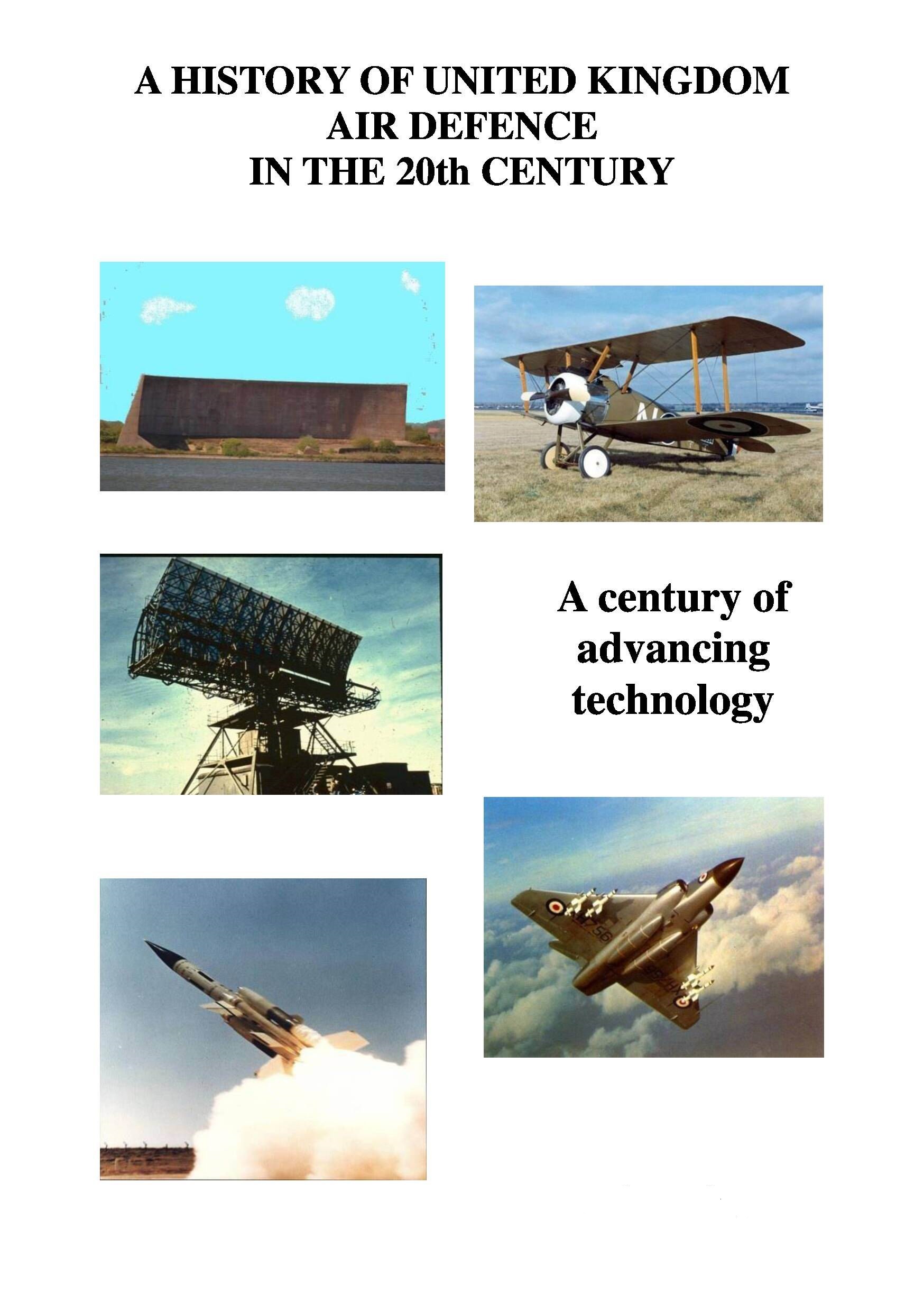
Count Von Zeppelin invented the Zeppelin airship. He flew his first machine on 2 July 1900. It was novel in two important respects. Firstly an internal combustion engine powered it. These had only been invented four years earlier in 1896. Secondly it had a strong internal metallic framework inside which there were the hydrogen gas bags. This framework enables it to travel at speed without distorting as had previous air balloons.
The Zeppelin was a huge aircraft. Count Von Zeppelin’s first Airship had a length of 128 meters and a diameter of 12 meters. The gasbag could hold 12,000 cubic meters of Hydrogen. It was powered by two 14.7 Daimler engines and could achieve a speed of almost 15 mph. Later military models had over 30,000 cu meters of hydrogen, travelled at speed of up to 80mph and could operate at over 14,000 ft. The airships could carry 2,000Kg of bombs and defended themselves with machine guns operated from the two Gondolas. Later models could operate at heights of up to 20,000 ft to escape attack but this caused great difficulties for the crew due to cold and oxygen deprivation.
ATTACK BY AIRCRAFT
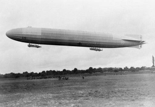
With the defeat of the airship attacks the Germans switched to attack by the Gotha bomber. This was the first heavier than air bomber to be used for strategic bombing. It carried a maximum bomb load of 1,000lbs, two machine guns and a crew of three. The first Gotha raid against England was in May 1917 when a raid of 22 planes bombed Folkstone causing 95 deaths. On 13 June 1917 fourteen Gothas carried out the first daylight raid on London killing 162 people, including 16 children in their classroom, and injuring over 400.
GOTHA GII BOMBER (3)
Then, on 7 July 1917 there was a raid of 22 Gothas on London. Although over 100 home defence aircraft responded to the attack the Gothas returned home relatively unscathed. The Gothas, which attacked at between 10,000 and 16,000ft and with a speed of 85mph, were initially relatively invulnerable because they were too high to enable the defences, using aircraft that climbed slowly, to intercept them as they flew up the Thames estuary towards London.
The outrage caused by these raids resulted in the Prime Minister, Lloyd-George, taking action with the result that a London Defence Area organisation was established and London air defences were greatly strengthened.
As defences against daylight attacks improved night raids began in August 1917 using both Gothas and Giants. At first the defences were not very effective and in the poor night time visibility on 4 September 1917, eleven German Gothas bombed London, killing 16 people.
Raids continued until May 1918, with increasing success by the defenders as a result of improvements firstly in early warning from sound sensors, secondly in gunnery success arising from better deployment and thirdly in improved tactics by the Royal Flying Club (RFC) and the deployment of the Sopwith Camel aircraft with a much better rate of climb than the earlier B.E.2c biplane. Fortunately after this date the Germans were retreating and their forces were withdrawn from attacks on Britain to fight elsewhere.
The Gotha bomber was a large aircraft with a wingspan of almost 80ft. It was powered by two Benz engines of 160hp, had a top speed of 90 mph and could fly at 10,000-16,000ft .
It carried a crew of three; a pilot, a rear gunner and a forward gunner. It also could carry 20 bombs of 50lbs each. By the end of the war it had undertaken 63 raids resulting in 850 deaths and approximately 2,000 injuries. Sixty two had been shot down, lost in crashes or had gone missing.
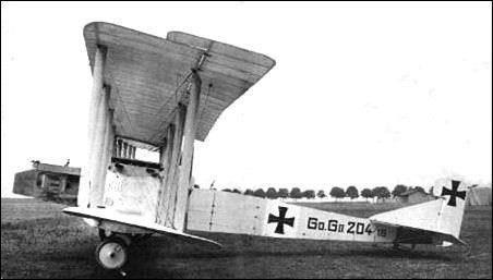
Count Von Zeppelin did not confine himself to airships. He was also involved in the manufacture of the Zeppelin Staaken “Giant” Bomber. Although only 30 of these were made they took part in night raids on London from September 1917 onwards.
The Giant was a much larger aircraft than the Gotha. It was a huge aircraft for the time with four 260 hp Mercedes engines, a wingspan of 138ft, a cruising speed of 80mph and a range of 500 miles . It could carry 4,400 lbs of bombs and defended itself with seven machine guns. None were shot down during their attacks on London.
GIANT (4)
THE DEFENDERS
At the start of the war Britain had very little in the way of air defences. The Royal Flying Corps had been established in 1912 but it was very weak militarily. The RFC had 84 front line aircraft and the Royal Naval Air Service had 71 aircraft and 7 airships. Most of the RFC forces had been sent to France and there was little to defend Britain. A few anti-aircraft guns and searchlights were available to defend London.
However by 1916 gun defences had been considerably strengthened and a number of Home Defence Squadrons had been formed.
By July 1916 the RFC had a total strength of twenty-seven squadrons (421 aircraft).The B.E.2c biplane was initially one of the mainstays of British home defences and it was this aircraft that was flown by Lt Leefe-Robinson when on 2 September 1916 he shot down the first Airship over England at Cuffley in Hertfordshire. He saw the aircraft lit up by searchlights and attacked by firing his machine gun into the underside of the airship until it caught fire. The sight of this airship falling to the ground in flames proved a great morale booster for Londoners and a great morale depressant for Airship crews.
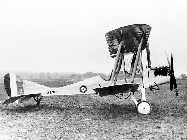
B.E. 2c (5)
Despite carrying an inflammable gas, hydrogen, Zeppelins had proved hard to shoot down because, even if the bullets penetrated the gas balloon, there was no oxygen to support combustion.
Eventually, by 1916, incendiary bombs and darts had been developed capable of igniting the fabric of the airships and the gas but these suffered from the disadvantage that they could only be used if the defender was above the airship. This was seldom the case because the airships flew high. The development of a gun using incendiary bullets by mid 1916 played a part in improving the effectiveness of aircraft defences.
The B.E.2c two seater aircraft was designed by Geoffrey de Havilland and F.M.Green of the Royal Aircraft Factory. It was unusual in design for the times due to the installation of ailerons on both the upper and the lower wings. The B.E.2c was developed for reconnaissance operations but some models were fitted with a Lewis machine gun and by December 1916, at least six Zeppelins had been destroyed by B.E.2cs. It had a 70hp Renault engine giving it a speed of 70 mph and a peak altitude of 10,000ft. In total some 3,500 aircraft of this type were built. The Home Defence Force was considerably strengthened by the delivery of Sopwith Camels, with a greatly improved rate of climb. This began on May 1917 and they saw first action in July.
The Camel was a highly manoeuvrable single seater machine but was difficult to fly partly due to the gyroscopic effect of its rotaryengine. However it was the highest scoring fighter in the First World War shooting down more German aircraft (1,294) than any other Allied plane. In total almost 5,500 were produced.
It was the first British fighter to have two propeller synchronised machine guns mounted side by side in front of the cockpit. It had a far better performance than the B.E.2c with a maximum speed of 110 mph and a service ceiling of 18,000ft, exceeding the normal top flight level of Zeppelins and equalling the Gotha.

SOPWITH CAMEL (6)
GUNS
At the start of the war there was little experience of anti-aircraft gunnery. In 1914 anti-aircraft gunnery was in its infancy and most of the deployed guns were field guns configured to fire upwards. Initially the Anti-Aircraft Brigade was formed from the Royal Marine Artillery. It was a very limited force with only four batteries each of which was armed with four Vickers naval guns each mounted on an armoured vehicle. The Vickers gun could only fire four rounds a minute. In the first design it had a limited range of 3,000 yards but improvements in ammunition progressively improved the distance the shells could travel.
Three gun Batteries were used to defend central London. However, in a response to air attacks on London and elsewhere, the gunnery capability was greatly expanded and by June 1916 Britain had 271 anti-aircraft guns, and 258 searchlights in position to defend targets against possible German attack.
Initially gunnery was so inaccurate that Londoners did not have much confidence in it. It was estimated that it took 15,000 shots to down an aircraft at the start of the war but, despite the lack of kills, the gunfire forced the enemy to fly higher and, eventually, as gunnery and aircraft defences improved, to fly at night.
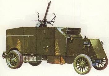
Pierce-Arrow Armoured Car and Vickers Anti-Aircraft Gun (7)
Ammunition was fused with a timer to cause the shell to explode when it reached the attacking aircraft without needing to impact. Because measurement of target range, hence time of flight of the shell, was the key to producing a better fuse time delay setting, the Height/Range Finder (HRF), was developed by Barr & Stroud. This was an optical coincident range finder 2 metres long on a tripod. It measured the distance to the target and the elevation angle, which together gave height. This greatly improved gunnery effectiveness.
It was clear that a purpose built anti-aircraft gun was urgently needed. After trying a modification to a 3.3inch army field gun in the anti-aircraft role, the Quick Fire (QF) 3in gun was developed. It was the first equipment designed specifically for the anti-aircraft (AA) role. This 3 inch gun mounted on a 20cwt vehicle was introduced in March 1914. It was a very effective gun and continued in service until the 1940s. At 45 degrees it had a range of almost 11,000yds with a rate of fire of 25 per minute and an effective AA ceiling of 23,000 ft. This was sufficient to attack the Gothas that operated up to 16,000ft.
Early designers of AA equipment mounted their guns on lorries that were easily available but because they were difficult to stabilise they were soon replaced by towed platforms. The QF 3inch gun was upgraded in 1937 to the 3.7 inch, (shown later) to make it effective to the height of 32,000 feet.
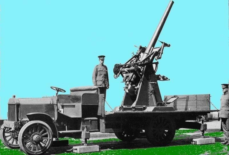
QF 3 inch Gun (8)
As Gotha raids on London intensified, in mid-1917 a barrage of 30 of these guns was set up on the eastern approaches to defend London. This had the effect of causing the Gotha to change tactics and concentrate on night time attacks.
The Gotha and Giant night raids continued throughout 1917, almost unscathed, until December when the defences began to have success with guns and the RFC, now equipped with the Camel, were increasingly successful in intercepting the Gothas at night.
BARRAGE BALLOON DEFENCES
Rather late in the War the defence of London was enhanced by the use of barrage balloons. They were deployed during 1917 and 1918 and they became an important element in the air defence system by constraining the freedom of attackers to use all the airspace.
In late 1917 the commander of Home Forces established a number of Balloon squadrons, in total some 3,500 people, to install and operate several balloon “aprons” on the east of London. Each Apron consisted of three balloons 500 yards apart joined together by a heavy steel cable.
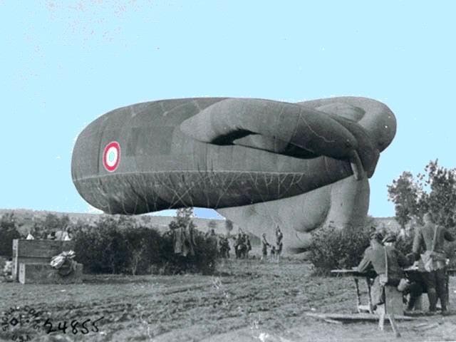
BARRAGE BALLOON (9)
These balloons had an operational height of 7,000 to 10,000 feet, and by June 1918 10 apron barrages shielded the northern and eastern approaches to the capital.
There is no recorded incidence of these balloons ever bringing down an enemy aircraft but they caused the enemy aircraft to fly in a smaller band of heights above 10,000ft and thereby enabled the gun and aircraft defences to concentrate on these height bands. Furthermore the Gothas were forced into flying high thus reducing the accuracy of their bombing. This led to a reduction in the frequency of raids
FINDING THE ATTACKERS
In the absence of radar the home defence forces relied upon observers on the coast to warn of impending attack. The London Metropolitan Observation Service was established with about 200 outposts. The service was staffed by policemen who used instruments to measure the bearing of the approaching aircraft and the angle of its course and report them to the Observation Service HQ at Horseguards, London. This enabled the defences to be prepared. Guns could be ready and aircraft could be directed to intercept enemy aircraft.
The warnings played an important part in deterring low level daylight raids so that the Germans had to attack at night or above 10,000 ft.
Of course, at night, it was difficult to see the aircraft and direct gunfire to them. Searchlights were used to help the gunners but it was difficult to ensure that the searchlight pointed quickly at the attackers. The searchlights were powered by electrical filament lamps or by acetylene gas hence were not very bright. The electric arc lamp was not invented until 1918.
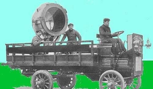
ELECTRIC SEARCHLIGHT (10)
Large hearing aids were used to locate attacking aircraft. The operator listened to the two horns separated horizontally and swung them around to determine the bearing of the target; then he used the horns separated vertically to determine the elevation of the target. Next he read off the elevation and the bearing and passed it to the searchlight operators and the gunners.
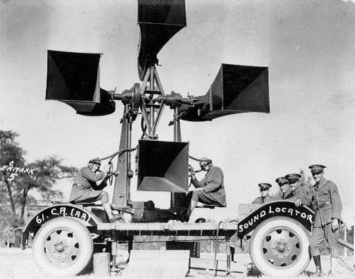
ACOUSTIC DETECTOR (11)
Frequently blind operators were used to man these equipment because of their superior hearing skills.
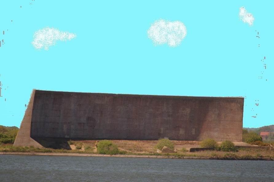
Acoustic detection was also sometimes used by the Observer Service to provide some early warning of air attack. Some large sound collectors were cut into cliffs in Kent as an aid to early warning of airships and aircraft. Also concrete sound collectors were built by the Royal Engineers as part of an extensive Zeppelin and enemy aircraft detection system deployed down the East Coast of Britain. The sound of approaching aircraft was reflected off the concave 'mirror' surface and received into a trumpet mounted on a steel column. The trumpet was connected to a stethoscope used by the operator or 'listener'. The part of the dish that produced the most sound indicated the direction of the approaching aircraft. Advanced warning of an imminent attack could then be given to local people and the Observer Service before reporting to the fighter stations.
THE INTER-WAR YEARS: 1918 TO 1935
At the end of World War One it was considered that Germany was no longer a threat and the Air Force was reduced by about 90% from over 3,000 squadrons to about 200. However, after a few years, the War Office became concerned about the build up of forces by the French. In particular they had an Air Force of over 600 aircraft whilst, in 1922, Britain had only 300 aircraft.
The politicians decided that Great Britain should have an Air Force at least as strong as that of any country that could attack us. Plans were prepared for a new defence system known as the “STEEL-BARTHOLMEW PLAN” soon followed by the “52 SQUADRON PLAN”. These plans were developed to defend Great Britain from a potential air attack by the French. The aim of these systems was to match the French Air Force strength for strength.
It was decided that the target strength was to be 35 bomber squadrons and 17 fighter squadrons. Though this level was never achieved, it did reach a strength of 42 squadrons by 1932. This aircraft strength was originally to be supported by a force of 200 guns with searchlight support. In practice this force also fell short, reaching barely 50% of its intended strength.
The plan was for central London to be defended by guns supported by searchlights with an outer belt of aircraft defences stretching around London, across the South of England and up to the Wash.
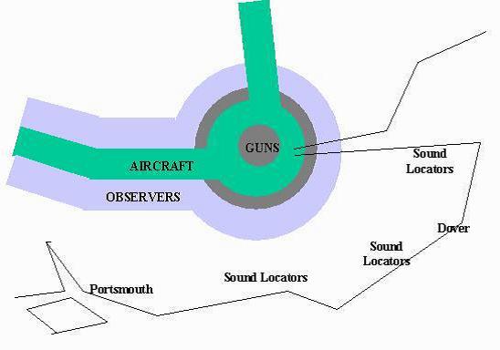
An outer ring of guns was provided to break up enemy attack formations before they entered the aircraft fighter zone. An extensive observer force named the Observer Corps was established in 1926 and a comprehensive communications network was developed. This was all brought together organisationally under the title of Air Defence of Great Britain.
By 1932 it was realised that the French were not the main threat as Germany began to re-arm extensively. The plan was revised by restructuring the Aircraft and Observer belt to cover the east coast from Dover to the Firth of Tees and the south coast from Dover to Portsmouth.
EARLY WARNING OF APPROACHING AIRCRAFT
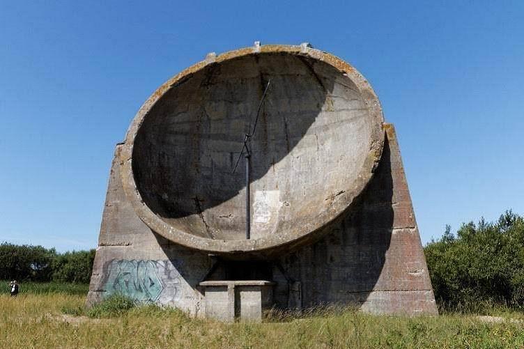
SOUND MIRROR (12)
The military were well aware that improved warning of the approach of air raids was needed. A plan was developed to improve the first world war sound alerting system and to use the noise made by approaching aircraft to give warning of an attack and thus provide an alert to the defensive forces. Large concrete sound collectors were built and installed on the South coast in Kent during the early 1930s. These measured 8-10 meters in diameter and on a quiet day could detect aircraft 20 to 30 miles away. This was some 20 miles before detection with the unaided ear and, as aircraft at this time flew at about 170mph, gave an early warning of some ten minutes. In the early 1930s the concrete sound collectors participated in the annual Air Defence exercises with the RAF.
The picture above shows one such collector. The operators sat in the hut in the centre below the dish and they could use the acoustic probe seen reaching to the centre of the dish to detect and, to some extent, find the direction of aircraft.
SOUND WALL (13)
Because it needs a large collector to collect low frequency sounds efficiently it was decided to supplement the acoustic detectors with large walls measuring 200 feet long and 26 feet high. Initially these used purely auditory detection but later they were fitted with amplifiers and microphones to improve their sensitivity. The picture shows the detector built at Lydd on sea
In spite of the limitations of this sound sensor system it was originally intended to defend the south coast from Swanage to The Wash with the early warning provided by three 200ft walls in the Thames estuary and a further twenty one for the remainder of the coast. It was also planned to have ten of the 30ft bowls installed in the estuary and four installed on the rest of the coast. The various sites were to be linked to defence headquarters by a telephone network. This plan was abandoned in 1937 after the early work on the newly discovered Radar had shown promise.
DEFENDERS DURING THE INTER-WAR YEARS 1918 – 1935
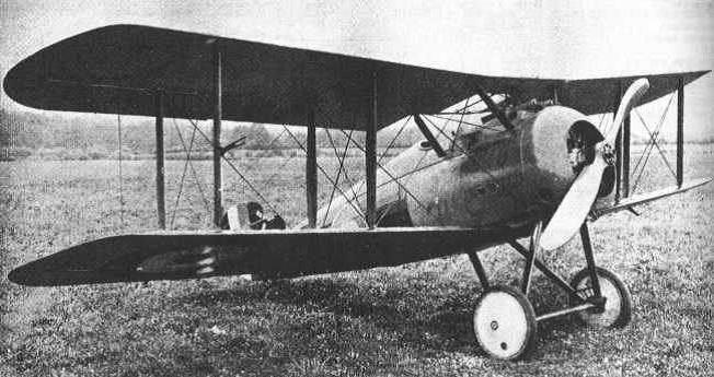
SOPWITH SNIPE (14)
The Sopwith Snipe was an improvement on the Sopwith Camel that had been widely used in WW1 as a fighter at home and abroad. It participated in operations at the end of WW1 then went on after the war to be a key aircraft in the RAF Home Defence inventory.
It had a 230hp Bentley rotary engine which enabled it to fly faster (121mph) and higher (19,500ft) than the Camel. It was armed with the standard set of twin, front mounted, Vickers 0.303 machine guns, and could carry four 20lb bombs under the bottom wing.
They started service with the RAF in 1917 and stayed as the only home defence aircraft until 1923, remaining in service until 1927.
In March 1927 the RAFs first all metal fighter, the Armstrong Whitworth Siskin entered service and became the RAFs principal fighter of that period with a maximum speed of 141 mph and a service ceiling of 21,600 ft .
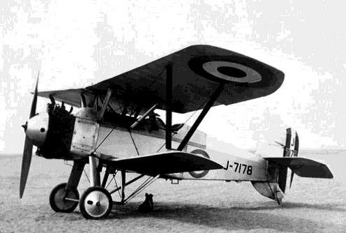
SISKIN (15)
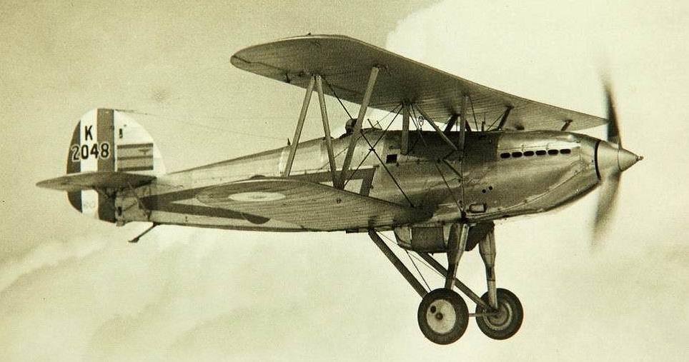
The Bristol Bulldog entered service in the UK in May 1929 and remained one of the most popular RAF fighters until 1936, employed mostly for home defence.

BULLDOG (16)
With a top speed of 175mph it was a single-seat fighter capable of operating in day and night-time conditions. It was armed with two 0.303 inch (7.7 mm) Vickers machine guns and powered by a radial air-cooled engine.
It was in this plane that Douglas Bader crashed and lost both legs after performing aerobatics.
MORE INTER-WAR PLANES
The Hawker Fury started service with the RAF in May 1931. It was the first RAF plane to have a speed of over 200mph in level flight and was therefore 30mph faster than the Bulldog. It was highly acrobatic and could climb at over 2,000ft per minute with a ceiling of 28,000ft and was powered by a supercharged 525hp Rolls Royce Kestrel IIS liquid cooled engine, and was armed with two Vickers III Machine Guns.
FURY (17)
This design led on to the Hawker Hurricane which entered service in 1937, and became one of the mainstays of the Battle of Britain. The similarity of fuselage shape is clear but the Hurricane was the first monoplane fighter of the RAF. It was also the first with a retractable undercarriage and an enclosed cockpit. It was powered by a Rolls-Royce Merlin engine, and was capable of over 300mph with a service ceiling of 36,000ft. It was armed with eight Browning machine guns in the wings.

HAWKER HURRICANE (18)
HOW DOES RADAR WORK?
You can think of a radar unit as a flash light. Instead of emitting visible light, radar emits invisible microwaves at a high frequency. The radar antenna sends out a short, high-power pulse of waves. When the waves hit an object, they echo from it and some power gets reflected back to the receiver. The time delay between the transmission and the receipt of the echo is used to determine the range of the reflector.
Usually the same antenna is used to receive the much weaker signals that return but in the early days of radar a separate receiving antenna was used. The width of the beam of radiation is set by the size of the antenna and the frequency of the microwaves. Larger antennas and higher frequencies produce narrower beams.
RADAR SCHEMATIC 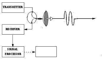
In the early days of radar operators had to look hard at the radar displays to see if a target was detected and to follow the target on the screen as the target moved. This was a very tedious job and could make the system slow to react to new threats.
In later years advanced signal processors were able to detect automatically and to track aircraft targets with no assistance from operators and this greatly speeded up the operation of the system.
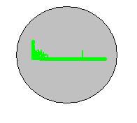
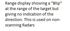
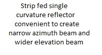
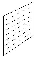
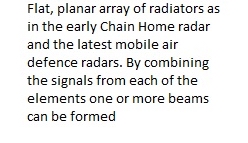
SOME COMMON RADAR AERIAL TYPES
PREPARATIONS FOR WAR 1935-1939
In the early 1930s the War Office were aware that the sound sensors only provided limited early warning and they sought new ways of detecting and disrupting air attacks. In February 1935 an experiment was conducted in which a Heyford bomber was flown though the beam of a BBC radio transmitter at Daventry whilst the received radio signal strength was measured. It was noticed that the received signal varied as the aircraft flew in and out of the beam. Thus the principle of radar was discovered.
Much further work over the next few years led to the installation, by the start of WW2, of a chain of radars from Ventnor on the Isle of Wight to the Firth of Tay. This radar chain played a vital part in the defences of Britain during the second world war.
The picture shows the radar site at Poling, Sussex, 1945. Wires supporting dipole transmitter antenna elements were strung between the three 300 ft tall towers to create an array aerial forming a horizontal fan shaped transmitter beam.
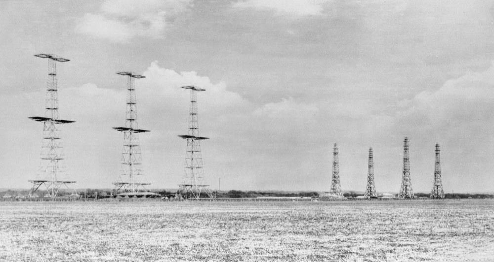
CHAIN HOME RADAR (19)
The four 200ft wooden towers shown on the right of the picture are used to support the receiver antenna. They are separated from the transmitter to prevent the high powered transmissions damaging the sensitive receiver. Transmissions were made at frequencies in the region of 20Mhz where the wavelength (15 Metres) roughly matched the wingspan of the target aircraft. A detection range of 130 miles was achieved with a claimed accuracy of one mile.
Effective though the Chain Home (CH) radars were, they suffered from the great disadvantage that they did not rotate hence it was difficult and slow for operators to determine the direction of the approaching aircraft and sometimes difficult to distinguish between a single aircraft and a multi aircraft raid. It also was not good at detecting low flying aircraft.
SOME FURTHER WARTIME DEVELOPMENTS IN RADAR
The Chain Home Low Radar was the first attempt to overcome some of the limitations of Chain Home. The initial versions of this Radar were scanned mechanically by pedal power driven by WAAFs. It operated at 200Mhz at a frequency ten times higher than that of Chain Home and had separate transmit and receive aerials. The operators had to align both aerials but the result was a beam about 25° wide, rather than the floodlight effect of CH.
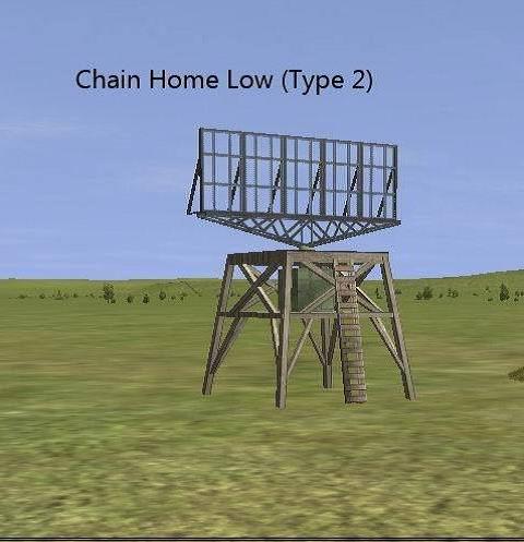
CHLR (20)
The aerials were not continuously rotated but, instead, were aimed at the target and moved from side to side to get the best reading of aircraft direction. Later versions of this Radar used a single transmit and receive aerial and rotated continuously under motor control. The Radar was frequently mounted on the top of one of the 300ft CH transmitter towers to improve its low level coverage.
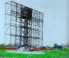
TYPE 7 RADAR (21)
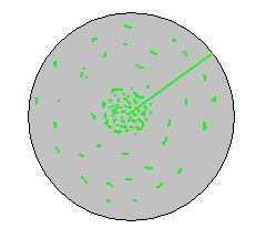
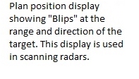
The Type 7 Radar was introduced into service shortly after the Chain Home Low Radar. This was fully rotating and used a common aerial to transmit and receive. It operated at around 200Mhz and had a beam width of 15 degrees. With a peak power of some 80Kw it could detect a bomber at about 90 miles. This Radar was the first to have a “Plan Position Display” in which aircraft are seen on a CRT showing 360 degrees of coverage.
To overcome the difficulty of sending signals to a rotating antenna some parts of the transmitter were attached to, and rotated with, the antenna.
This Radar was also capable of producing a good indication of the height of aircraft detected. It enabled controllers to direct fighters to intercept enemy aircraft by watching both aircraft on the radar display screen – a facility that came to be known as Ground Controlled Intercept (GCI).
Early versions of this Radar were used in 1940 and later versions from 1942 to the end of the War.
THE OBSERVER CORPS
The Observer Corps (OC), based upon the earlier WW1 Metropolitan Observer Service, was established in 1926 under Army control. Initially it consisted of three hundred volunteers who were sworn in as Special Constables whose duties also included observation work and who worked in their spare time to spot aeroplane activity.
However once war broke out it was realised that they could perform a very important function in supplementing the information provided by radar. The Corps played a vital role during World War II giving advance warning to Fighter Command of incoming enemy aircraft as well as plotting their position and movements. The Corps volunteer members became highly skilled in the field of aircraft recognition as a result of this. By 1940, over 1,000 OC posts had been established. Its manpower was greatly increased, eventually reaching a strength of 32,000 with over 1,400 observation posts largely on the south and southeast coasts. In 1941 it was renamedThe Royal Observer Corps.
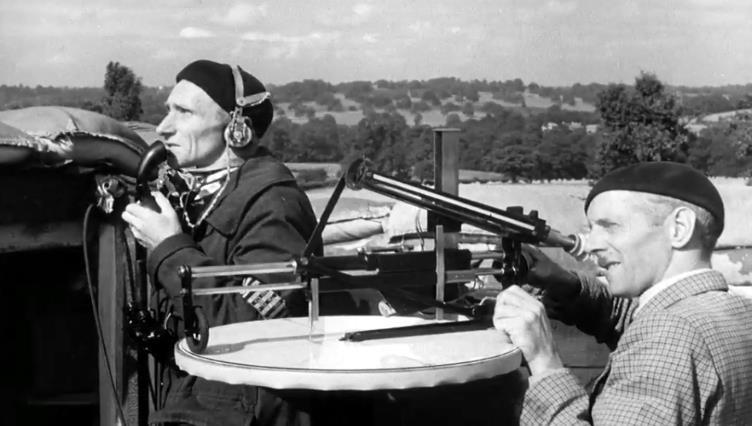
THE OBSERVER CORPS (22)
The staff of the Observer Corps were trained in aircraft recognition and in aircraft height estimation. They were tasked by Group HQ once the HQ had been alerted to the approach of a raid by Chain Home Radars. Their role was to estimate the aircraft strength and height of raids once they were over land and therefore had often passed out of the coastal radar cover. The individual observer posts of three to five men would look and listen for the approaching raid. The control network is shown below.
.jpg?timestamp=1572013574224)
THE CONTROL NETWORK (23)
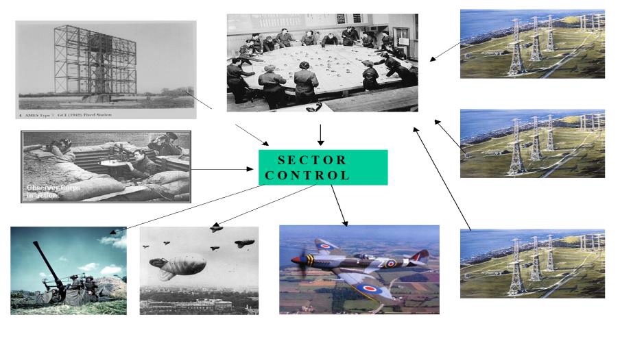
GROUP HQ (24)
The diagrams above show the main information flows.The information flow and aircraft control network was complex. Aircraft positions (Plots) from the Chain Home Radars along the south and east coasts were passed to the local radar station where the detections of enemy aircraft were plotted on a map.
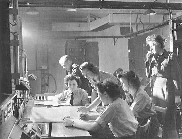
The Plotting Room at RAF Bawdsey during WW2. (25)
When radar operators were satisfied that they had accurate data they passed the raid information, by telephone, to the filter room at Fighter Command Head Quarters (FCHQ).
The filter room at FCHQ received aircraft and raid position reports from many radar sites. Here any ambiguities in the information arriving from the various radar sites linked to HQ Fighter Command were removed and operators created an air picture in which all the aircraft were placed into categories such as friendly, hostile and unidentified. The agreed picture was then passed to the relevant Air Defence Group HQ which, for the Southern Command, was at RAF Uxbridge.
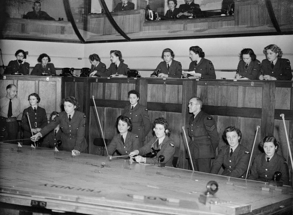
WAAF plotters at work in the Operations Room at No. 11 Group HQ at Uxbridge in Middlesex, 1942. (26)
At Group Headquarters commanders allocated tasks to sectors according to geographical position of the threat or the availability of defending fighters in the area covered by the sector. The sector commanders then used information from local radar stations using the Chain Home Low Radar, information from the Observer Corps and information about the availability of aircraft resources to decide on the response to the threat. This response could employ gunnery, barrage balloons and fighter intercepts. If attacking aircraft were within cover of the Type 7 CHL Radars Ground Controlled Intercept could be employed.
In the early days of the war friendly aircraft returning from a mission could easily be confused with enemy attackers. Friendly aircraft made themselves identifiable by responding to instructions by the controller to change course so that their radar blip moved accordingly. This approach to identification was later enhanced by fitting a radar reflector with fluctuating reflectivity to friendly aircraft so that the controller could observe the fluctuation of the radar echo on the screen. Later a system known as PIPSQUEAK was introduced. This used the pilot's radio to transmit a signal regularly so that the friendly aircraft could be located by the radio-frequency direction finding (DF) system. This position fix assisted the filter station in identification.
As the war progressed better and better means for friendly aircraft identification were developed. Eventually aircraft were fitted with transponders that reacted to interrogations from signals sent out from a supplementary radar attached to the main radar antenna. After the aircraft had been identified and categorised the tidied up air picture was passed to the air defence commanders at Fighter Group headquarters.
AIRCRAFT RADAR
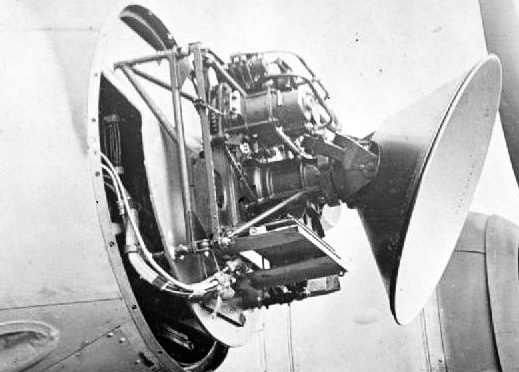
Ground Controlled Intercept could be used to direct aircraft to close proximity to the attackers but at night, or if visibility was poor, interception might still be difficult. Ideally radar is required on the fighter aircraft to assist the pilot to intercept the enemy aircraft. The Mosquito night fighter shown below was fitted with one of the early Air Intercept (AI) Radars. The aircraft entered service with this radar in January 1942. The radar antennas can be seen,(with difficulty!) on the aircraft nose (transmitter) and on the wing tips(receivers).
This Radar had a fixed beam hence it produced a range indication but it could produce only crude directional information as the pilot swung the aircraft from side to side to optimise the signal, but it greatly assisted the Mosquito in homing in on the attackers. The Radar operated at a frequency of 195MHz.
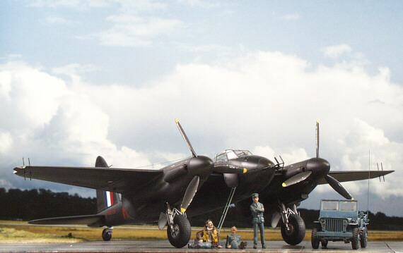
MOSQUITO WITH AI RADAR (27)
By 1943 the German Air force was using the Juckersaicraft, in its fighter bomber configuration, with an AI Radar using the rather complex aerial system shown here.
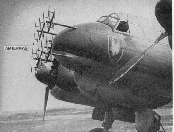
Low-UHF band airborne intercept radar, using the complex 32- dipole Matratze antennas (27b)
The invention of the magnetron in 1940 by Randall and Boot at Birmingham University led to the development of Radars operating at 3Ghz (10cm wavelength) and above. At these frequencies it was possible to have both a narrow beam and a small aerial. This enabled radar with small scanning aerials and narrow beams to be developed
These Airborne Intercept (AI) Radars with scanning aerials were fitted to Mosquito aircraft and by mid 1942 were undertaking night time operations.
The photograph below shows a 28 inch diameter scanner fitted to a Beaufighter aircraft. Due to the introduction of AI Radar the casualty rate of enemy night bombers was raised from less than 0.5% to over 7%.
MICROWAVE AI RADAR (28)
The first Beaufighter twin engine fighter bombers entered service in early September 1940. The first night operations took place in September and October 1940 and on the night of 19/20 November 1940, a Beaufighter IF, equipped with AI radar downed a Ju 88. More advanced radar units were installed in early 1941, which soon allowed the Beaufighter to become effective counter to the night raids being performed by the Luftwaffe.
WARTIME DEFENDERS
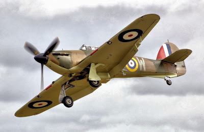
HAWKER HURRICANE (29)
The Hawker Hurricane was delivered to the RAF in October 1937. Fortunately by the start of the Battle of Britain the RAF were in possession of 497 of these aircraft and they were responsible for 80% of all enemy aircraft shot down in the battle. They were mainly used to attack bombers whilst the more agile Spitfires attacked the fighter escorts to the raids.
In addition to the Hurricane, air defence was provided by the Supermarine Spitfire. This was the second of the RAF's eight-gun monoplane fighters. Initial models were powered by the Rolls-Royce Merlin II engine of 1,030hp. This gave the Mk I a speed of 355mph, a height ceiling of 34,556ft. It was equipped with eight Vickers machine guns, four in each wing. A total of 1,583 Mk Is were made.
Later models achieved 450mph and there were variants on the armaments to suit its differing roles. It was delivered to RAF Duxford nine months after the first Hurricanes had been delivered. By 1942 Fighter Command had 60 squadrons of Spitfires.
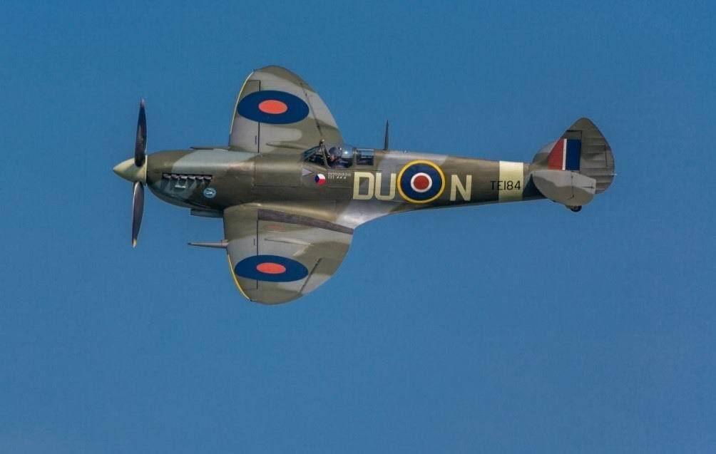
SPITFIRE (30)
The De Havilland Mosquito fighter bomber and night-fighter entered service in 1941. The Mosquito was a twin engine aircraft with the pilot and navigator sitting side-by-side. It was of unusual construction being made largely of wood and was known as “the wooden wonder”. This gave it the advantage that it was easy to repair after battle damage.
Powered by two Rolls Royce engines of 1,700hp it had a speed of up to 415 mph and a ceiling of 37,000ft. It was armed with four 0.303 machine guns in the nose and four 20 mm cannons under the nose. It became the standard night fighter of the RAF, and was fitted with an AI Radar to assist target location particularly at night.
In all 7,781 Mosquito aircraft were built. It was successful against the V1 bomb and claimed 486 kills.
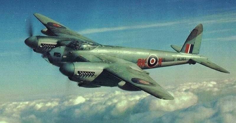
MOSQUITO (31)
GERMAN WW2 BOMBERS
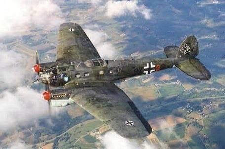
HEINKEL 111 (32)
Four of the main threat bombers during the blitz were the Dornier Do 17 and 217, the Heinkel 111, the Junkers Ju 88 and the Focke-Wulf 200.
The first heavy raids on London came on September 7 1940. Over 300 bombers escorted by 600 fighters came over London starting in the afternoon. This was the first of 58 consecutive nights of bombing attacks on London.
The Heinkel 111 first flew in 1936 as an airliner for Lufthansa. It was a medium bomber. Early versions carried 3,500lbs of bombs while later models could carry twice this amount. It had a maximum speed of 227mph and a range of 1,200 miles. The He111 was the main Luftwaffe bomber during the early stages of World War II, and it played a key role on the German side of the Battle of Britain. Later in the war it was used to launch V1 bombs against London.
The Dornier Do l7 which first flew in 1934 was originally designed as a commercial airliner. It was redesigned as a medium bomber and long range reconnaissance aircraft. The bomber was known as “the flying pencil” because of its slim fuselage. It was soon slightly modified to create the Dornier 215. Both the D17 and the D215 took part in the London Blitz in September 1940. A D17 shot down by a Spitfire was the first recorded kill of the Battle of Britain.
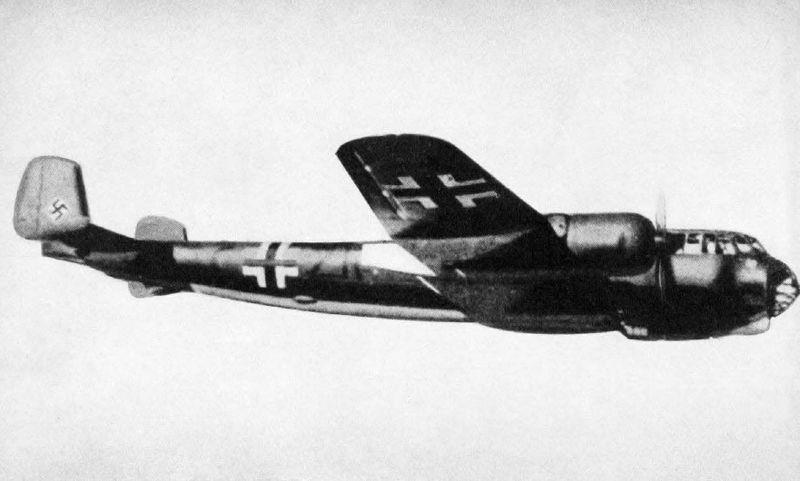
DORNIER 217 (33)
In 1938 work began on an improved military version, the 217, with double the bomb capacity. This entered service with the Luftwaffe in 1940. It was capable of flying with 4,000lb bomb load, had a crew of five and its two 1,000hp engines gave it a speed of 265 mph, a range of 720 miles and a ceiling of 26,740ft.
The combat version of the 217 flew in late 1940, and it was used in the closing days of the Battle of Britain. The bombers were escorted by a defence force of the Luftwaffe’s principle fighter, the Messerschmitt ME-109. This had limited range and was operating from bases some way from Dunkirk, making the German bombers very vulnerable to the most modern RAF fighters.
The Me 109 was the principal German fighter. However, with a range of 700km, it had only 15 minutes fuel over Kent and was at the limit of its. range over London. The two engine ME-110 had a slightly longer range.

Me 109 (34)
FINDING THE BOMBING TARGET
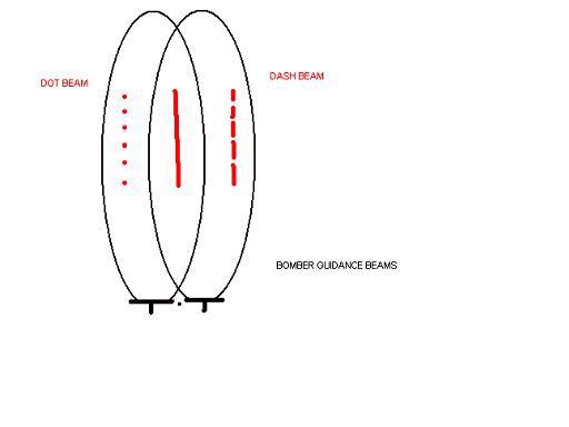
At the start of the war German bombers bombed in the daytime but losses increased due to the effectiveness of Chain Home Radar and Airborne Intercept Radars. They then started to bomb at night when effectiveness was greatly reduced as they had no bomb aiming radar. The German bombers relied upon a system of navigation beams transmitted from Germany to direct them to their targets. If the bomber was to the right of the correct direction to the target the pilot heard a series of dashes on his radio; if he was to the left he heard a series of dots. On the centre line he heard a continuous note. This scheme was initially successful but eventually the British discovered ways to jam the beams thus sending bombers off target. Because of the jamming a more complicated system was developed that required greater skill in its use.
A small flight of planes with crews skilful in following the beams led the flight, dropping incendiary flares to mark the target. The British countered with "Starfish" - decoy fires lit to lure the main mass of bombers away from the target.
The Germans developed a more refined system which depended on a transponder and this was countered by using the BBC transmitter at Alexander Palace to send false responses. Alexander Palace was then bombed! But by that time we had developed such advanced AI radar that the Germans decided they were losing too many bombers to continue with the raids.
In addition to jamming the navigation beams to send the bombers off target the War Office engaged the cinema industry experts in a campaign to create dummy targets to attract enemy bombs. This lead to the development of dummy airfields for use in daytime and night time together with representations of burning buildings to attract “second wave” bombers.
By 1940 there were 60 dummy daytime airfields in Britain. They had moderate success, attracting 30% of the air strikes in the first 6 months of 1940. One hundred night time dummy airfields were established by the end of 1941. Car lights were used to represent aircraft lights and moving lights modeled taxiing aircraft. They were very successful and in the period June to October 1940 they absorbed 60% of the total airfield attacks.
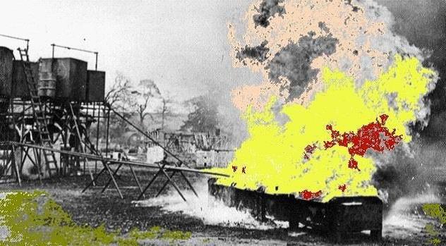
Oil Tanks feeding a mock building fire (35)
By 1943 the numerous mock city fires had also attracted many bombs away from the cities providing a great morale boost to the population.
MOCK AIRFIELD (36)
THE DAWN OF THE MISSILE AGE.
The German V1 Rocket, colloquially known in Britain as the 'Doodlebug', was the first cruise missile and had a range of about 200 miles. It had a length of 26ft, a wing span of 17ft and travelled at a speed of 350 to 400mph. The missiles weighed 2 tonnes and had a 200lb payload.
Hitler authorised full development work on the V1 in June 1942. It was an economic weapon to produce being built of cheap materials and was easy to manufacture. Compressed air cylinders were used to power the jet fuel injection system and also the missile control surfaces. The very simple navigation system was sufficient to enable it to hit a target the size of London.
The first V1 used against England dived to the ground and exploded inGrove Road, London E4 at 04.25 on the morning of 13th June 1944, a few days after the D-Day landings. Altogether on that day ten V1s were launched at London but only four reached the city. Initially aircraft defences were not very successful due to the high speed of the missiles and because it was dangerous to be close to them when they exploded.
New tactics included tipping them over with a wingtip or flying so that they were in the defenders slipstream caused many of them to crash harmlessly. Also, improved defensive tactics including the use of the Hawker Tempest aeroplane and creating a powerful gun belt near the coast, soon improved the kill rate.
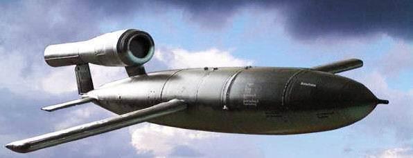
VI MISSILE (37)
This, combined with greatly improved gunnery effectiveness due to the development in the USA, in collaboration with the British, of radar based automatic gunlaying, and of the proximity fuse, led to the defeat of this threat. The last doodlebug was launched in October 1944.
More than 9,000 V1s were launched against London alone causing. 5,475 deaths and injuring 16,000. Almost 2,000 were shot down, 2,000 destroyed by aircraft defences and 300 were brought down by barrage balloons.
The Germans then moved on to using the V2 Rocket. This was the first long range Ballistic Missile. The V2 was a huge missile, 46 ft tall, with a diameter of 6ft and carrying one ton of High Explosives. It weighed 13 tons and travelled via thestratosphere at 3,000 miles an hour.
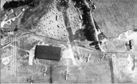
It was launched vertically from a mobile transporter so it was difficult to attack the launch sites. On 8 September 1944 the first V2 fell on Staveley Road, Chiswick, London with no warning.On 27 March 1945,Mrs Ivy Millichamp, aged 34, of Orpington Kent, was the last person to be killed by a V2 in Britain.
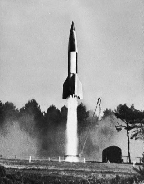
V2 Missile (38)
More than 1,300 were launched between September. 8 1944 and
March 27 1945, against London and S E England. 2,724 people were killed, and 6,000 were seriously injured by the weapon Fortunately the launch sites were over-run as defence forces advanced and attacks ceased.
ANTI-AIRCRAFT GUNNERY
By the start of WW2 anti-aircraft weapons were considerably advanced compared to those of WW1. Fire rates were much increased. Typical was the Bofors 40mm gun (below, left) with a maximum fire rate of 80-100 rounds per minute used for low level air defence, and the QF 3.7inch (94mm) (below, right), with a fire rate of 10-20rpm, used up to 32,000ft.
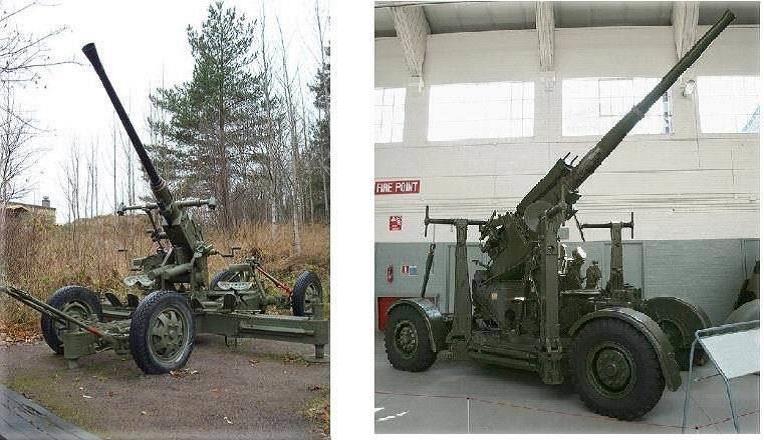
GUNS (39) GUNS (40)
Initially these used time delay fuses or barometric fuses but later in the war had proximity fuses based upon a radio transmitter in the shell.
As in the first world war, before radar was invented, sound detectors were initially used by the Army to help direct searchlights and guns onto attacking aircraft.
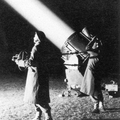
Radar was soon applied to assist gunnery. Here the photos show a 90cm searchlight with a Searchlight Control (SLC) AA No.2 Mk7 Radar. The Radar, operating at about 200Mhz, enabled the searchlight to track enemy aircraft accurately for visually directed AA fire. The Radar also included an identification (IFF) capability to limit friendly fire losses.
Radar Directed Searchlight (41)
By 1942-43, the system (pictured above) became semi-automated and searchlights (and anti-aircraft guns) could be fitted with a radar that could track a target automatically.
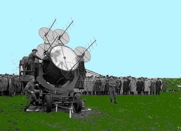
After the discovery of the magnetron, collaboration with the USA led to the development of highly accurate gun laying radars. The SCR584 shown schematically, deployed below, enabled major improvements in gunfire lethality to be achieved.
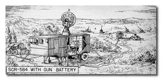 SCR-584 (42)
The radar would automatically track the hostile aircraft and direct the guns to follow it. Using systems such as this, the threat from the V1, “Doodlebug” was greatly reduced with lethality in engagement reaching over 80%. The kill rate rose from 20,000 shells per hit at the start of the war to 4,000 shells per hit.
The 93rd Searchlight Regiment was the only Army regiment staffed mainly by women. Searchlights, which were operated with the gun defences, were active against German raids flying over Britain on most nights from the beginning of June 1940 onwards. They were more plentiful than guns, nearly 4,000 being available towards the approved total of 4,128. In daylight they had the important function of reporting air activity to the gun operations rooms.
SEARCHLIGHT (43)
In addition to the hazards of searchlights, guns and defensive fighters, attackers had to contend with barrage balloons around key points. In November 1938 RAF Balloon Command was formed. This Command operated barrage balloons on the approaches to London and at other important sites.
The command rapidly expanded and by the end of July 1940, 1,466 balloons were in service, 450 of which were required for the defence of London. The balloons were filled with about 20,000 cubic feet of hydrogen gas and flew high enough to force the attackers to fly high where their bombing accuracy was reduced. It is interesting to note that the German Ju 88 V7 bomber was fitted with cable-cutting equipment to combat the potential threat of British barrage balloons, and was successfully tested in this role.
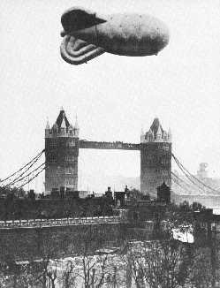
BARRAGE BALLOON (44)
The height of the air war over Britain, when our defences were stretched to their limit, was during the Battle of Britain culminating in the Blitz on London. It was the enemy aim to gain air superiority as a prelude to an invasion. After a sustained attack in the early part of August 1940 in which the RAF lost over 200 fighters and 100 pilots, losses continued at this level until the end of August. German losses were also at a high level and in early September Hitler ordered a change of tactics with instructions to the Luftwaffe to bomb London into submission. During the Blitz that lasted until May 1941, over 18,000 tons of bombs were dropped on London. 20,000 people were killed and 1.4 million made homeless. The Blitz ended in mid 1941 after Hitler had decided to attack Russia.
THE EMERGING SOVIET THREAT
With the end of the war much of the wartime defensive sites were dismantled as peace reigned. In 1948, the Soviet Union blocked access to the three Western-held sectors of Berlin. Then in 1949 the USSR exploded an atomic weapon and in 1950 tension rose further with the start of the Korean war.
It was known that work on a long range bomber, capable of striking at targets deep in enemy territory had begun in the Soviet Union in 1943. after three American B-29 bombers flying against Japan had landed in Siberia and had been seized by the Soviets.
The TU-4 was essentially a copy of the US B-29 bomber. It was a four-engine, propeller driven, medium bomber with two bomb bays centrally located in the fuselage. Defensive armament consisted of four turrets located in upper forward, lower forward, lower rear, and tail positions. It had a speed of 558 km/h and an operational range of 5,400Km.
It was this aircraft that dropped the first Soviet atomic weapon that was delivered by aircraft on October 18, 1951.
The deployment of the TU-4 bomber began in 1949. When production of the TU-4 finally ended in 1952, a total of 847 bombers had been produced.
There was therefore great concern that the USSR might launch a surprise attack on the UK using Tupilov long range bombers with nuclear weapons.
TU-16 (Badger) Bomber (45)
The TU-4 was replaced by the TU-16 bomber that entered service in 1954. This was essentially an enlarged TU-4 but was powered by two turbo-jet engines, had a speed of up to 900km/hr and a greater combat radius than the TU-4. Early models could carry 18,000lbs of free fall conventional bombs or nuclear weapons and later models could be armed with Air to Surface weapons. Some of these aircraft were designed specifically to jam opposing radar systems.
THE ROTOR DEFENCE SYSTEM
The Top Secret ROTOR programme was launched in 1948 with the objective of providing a bomb resistant defence system with radar cover all around the United Kingdom.
In order to be resilient against possible attack by nuclear weapons the Rotor Air Defence Control rooms were buried in bunkers designed to be capable of withstanding a nearby strike from a 20 kiloton atomic bomb. There were over 60 bunkers mostly at RAF stations on the East Coast. Some had a single level but others were on two or three levels.
The entrance to many of the Bunkers were inside what appeared to be a guard room.
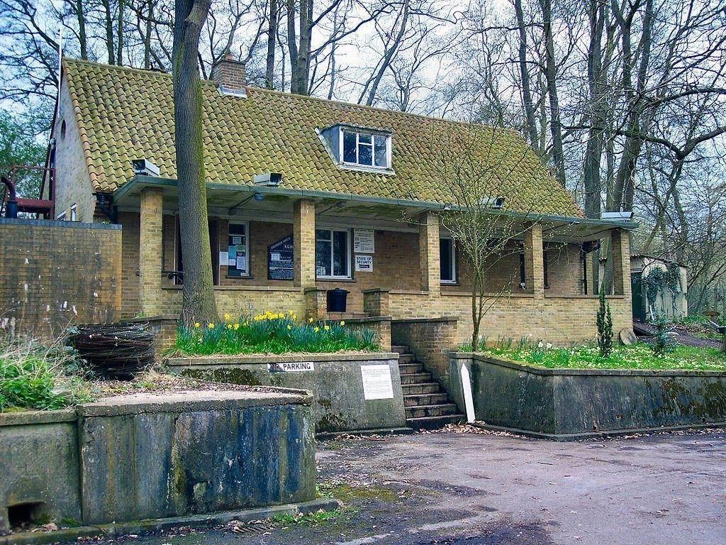
"A NOW RATHER OVERGROWN GUARD HOUSE" 46)
From inside the guard room a long passage led down into the heavily reinforced concrete bunker. Some of the larger bunkers had outer walls constructed of 10 foot thick ferro-concrete utilising some 30,000 tons of concrete. In the operations room it was possible to monitor the radar pictures to detect the threat aircraft.
Other rooms contained the equipment to maintain communications with friendly fighters and with elements of the defensive command structure at other sites. Some bunkers were used as anti-aircraft gunnery operations rooms.
ROTOR RADARS
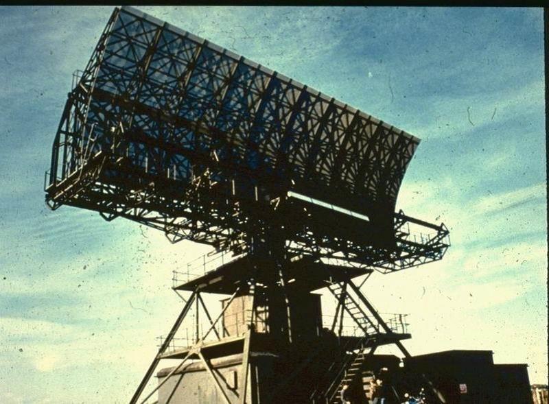
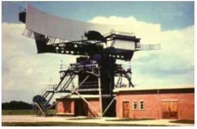
Rotor radar cover initially depended upon refurbished Chain Home Radars but was enhanced by the AN/FPS 3 Search Radar purchased from the USA as an urgent measure to upgrade the UK radar cover. It operated at the microwave frequency of 1Ghz and rotated at speeds of up to 10 rpm. These were installed from 1952 at a number of RAF sites. As can be seen from this picture the radar had four horns illuminating a double curvature dish hence creating four elevation beams to aid aircraft height determination.

AN/FPS3 (47)
TYPE 80 RADAR (48)
The Type 80 Radar was the first UK developed Microwave (3Ghz) radar. It was installed after 1953 to provide cover all around the UK. It rotated at 4 rpm and with an antenna measuring 75ft by 25ft had a 0.3 degree azimuthal beam with a wide vertical coverage.
With a peak power of up to 2.5Mw the performance was so good that it was possible for long range early warning and Ground Controlled Intercept (GCI) to be performed from the same site.
Hence there was a major reorganisation of the information management of the defence system into the Master Radar Site (MRS) system. In this arrangement some radar sites undertook aircraft control functions with the result that the reaction time of the system was considerably shortened because there was no need to send plot and track information to the filter centre and then to the Sector operations centre.
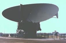
The long horizontal microwave feed to the front of the vertically curved dish generated a single narrow width but broad vertical beam so the radars were supplemented with a special purpose height finding radar (shown below).
The FPS 6 Radar was supplied from the USA to enable the height of possible attackers to be measured accurately. It had a single horn
illuminating a tall narrow double curvature dish to create a narrow beam in elevation that was scanned up and down as the antenna nodded. The operators noted the elevation at which the aircraft echo reached a maximum value to determine height. The radar entered service in 1952. In later years a height finder developed in the UK was also installed on some sites.

FPS 6 (49)
ROTOR AND MASTER RADAR SITE DEFENCES
By the early 1950s aircraft technology had advanced considerably due to the impetus of the war years. The RAF air defence aircraft were now jet powered, and were soon supersonic and fitted with air- to- air missiles.
The Gloster Meteor Mk. I saw action for the first time on July 27 1944 against the V1 Flying Bomb and in a number of variants continued to be supplied for about 10 years. It was the RAF's first jet fighter and the only turbojet powered aircraft flown in combat by the Allies during World War Two. With a operational speed of up to 600mph it beat the world speed record on a number of occasions. It was armed with four 20 mm British Hispano 5 cannon in the nose, two each side of the cockpit. The night fighter version began to be phased out in 1953 but the night fighters continued for some years.
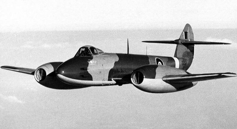
GLOSTER METEOR (50)
The Hawker Hunter entered service 1954. It was the RAF's first supersonic aircraft with a speed of up to 750 mph, a ceiling of 50,000ft, swept wings, a single turbojet engine with intakes in the wing roots, and a high-mounted tail plane. It was armed with four 30mm ADEN cannon in a detachable pack in the nose, with under wing fittings for bombs and rockets..
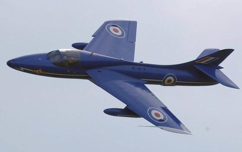
HAWKER HUNTER (51)
The Gloster Javelin entered service in February 1956. It was the first RAF plane of the Air to Air missile era, being armed with four Firestreak heat seeking missiles, and the world's first twin-jet delta wing fighter. It was capable of Mach 0.95 at altitude and was used as a day and night fighter. It was designed for bad weather operations, flew at 600mph at 40,000ft. and had a 52,500ft ceiling. It ceased operations in 1968.
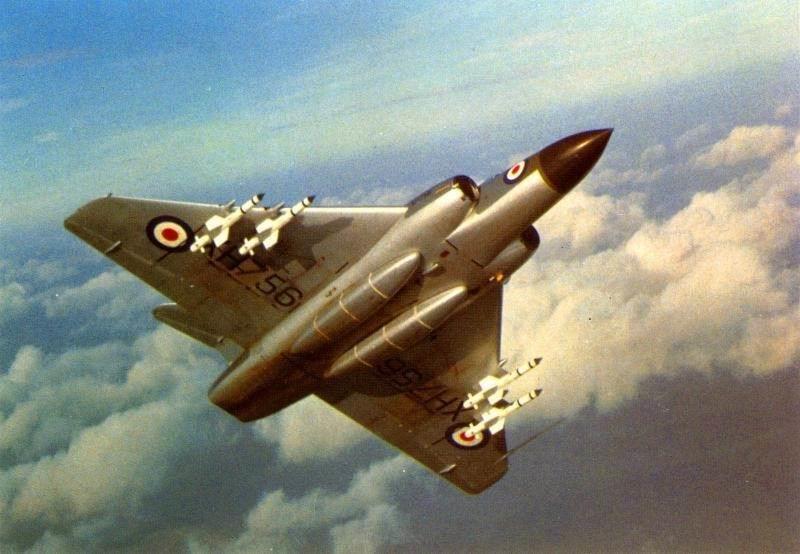
GLOSTER JAVELIN (52)
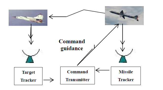
MISSILE GUIDANCE
There are several different ways to guide a missile to its target. One of the simplest is for the missile to follow the beam of a radar pointing at the target. This is known as beam riding. Command guidance is similar to beam riding because the target is tracked by the defence system radar but the missile is tracked by a second radar. The command transmitter instructs the missile onto an intercept path.
At the final phases of an engagement, the homing phase, great accuracy is needed to ensure that the missile gets close to the target. In active guidance the missile radar illuminates the target and homes in on the reflected signal.
Active Guidance
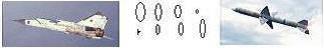
In semi-active homing the target is illuminated from the attacking ground based or airborne weapon system and the missile homes as in the active system.
Semi-active homing
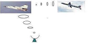
In passive homing systems no illumination is needed, The missile homes in on the heat emitted by the target or, should the target be trying to jam the attacker's radar, on microwaves sent out by the target's electronic systems.
Passive Homing
FIRST RAF AIR TO AIR MISSILES
The RAF has used both Infra Red heat seeking missiles and Radar guided air to air missiles.
Fireflash was the United Kingdom's first air-to-air guided missile to see service with the Royal Air Force. It was briefly deployed during the 1950s.The missile utilised radar beam riding guidance. The RAF deployed the later and more effective Firestreak infra-red homing missile from August 1958. It was deployed on the English Electric Lightning, the de Havilland Sea Vixen and the Gloster Javelin. It was a rear aspect fire-and-forget pursuit weapon with a field of attack of 20 degrees either side of the target.
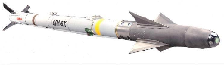
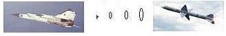
Sidewinder Missile (53)
Development of the Sidewinder began in 1949 in the USA with the aim of producing the World’s first Infra-Red (IR) homing missile. The AIM-9 Sidewinder is a supersonic, heat-seeking, air-to-air missile carried by fighter aircraft. It has a high-explosive warhead and a passive infra-red guidance system.
Early versions of this missile were capable of rear attack using the heat from the engine output as a hotspot target. Later versions became more sensitive and could attack from all directions; even later versions used a thermal imager to identify the more vulnerable parts of the target aircraft.
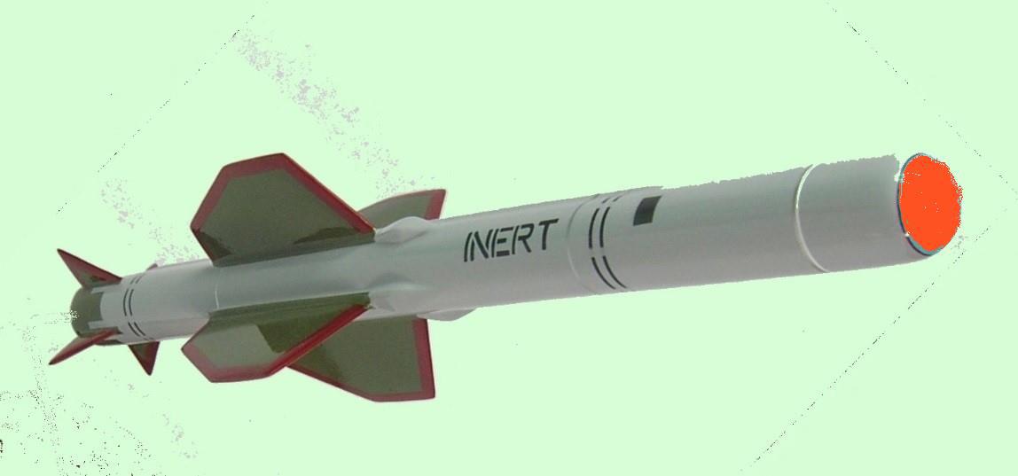
Red Top (54)
The Red Top missile was developed in the UK after the early versions of the AIM-9 missile were available with the aim of improving the Infra-Red seeker heads to such an extent that a target aircraft could be engaged successfully from almost any direction. The missile had a speed of Mach 3.
Heat seeking missiles are short ,within visual range weapons, and have the major benefit for the attacker that, once they have locked onto a target, the launching aircraft can turn away from the engagement and seek safety or move on to another engagement. This is known as a “Fire and Forget” capability.
Development of Red Top was rapid and it entered service in 1964 with Lightning Squadrons.
Radar guided missiles have the advantage that they can operate at beyond visual range, allowing the possibility of missile launch before the opposition can fire.
The US developed AIM-7 Sparrow medium-range semi-active radar homing was fitted to RAF Phantom aircraft. Later the Sky Flash a medium-range semi-active radar homing air-to-air missile derived from the Sparrow missile was carried by Royal Air Force F-4 Phantoms and Tornado F3s
ROTOR POINT DEFENCES
Bloodhound was developed during the 1950s as the UK's main air defence weapon and was in large-scale service with the RAF defending east coast air defence sites. It was the RAF's only long range Surface-to-Air missile and was used by the RAF for almost the entire Cold War being deployed from 1958 to 1991. It was used initially to protect the V-Bomber bases that were home to the UK strategic deterrent.

BLOODHOUND (55)
Bloodhound was a large missile over 21ft in length and with a weight of 2 tons. Its two Thor ramjet engines with four solid fuelled boosters gave it a speed of Mach 2.3 and a range of 120 miles.
It employed a semi-active terminal phase homing in on the microwave energy reflected from the missile. With a radar to track and illuminate the missile and another to track the target the missile flew directly to the intercept point rather than in the ever changing direction towards the target. It had a radio proximity fuse to explode the warhead when the missile was close to the target.
![]()
BLOODHOUND (56)
THE RUSSIAN THREAT OF THE 1970s AND 80s
The Soviet Tu 95, known to NATO as the Bear Bomber, had six radar-controlled turret-mounted AM-23 guns for self-defence, could carry 9,000kg of bombs and one 500km range air-to-surface weapon. It had a combat speed of 470km/hr and was powered by four turbo-prop engines with eight propellers. It entered service in the late 1950s. In the 1960s and later, the Badger and Bear aircraft made regular incursions into UK northern airspace and were monitored by UK Lightning and Phantom fighters. .(though the picture shows a US escort.)
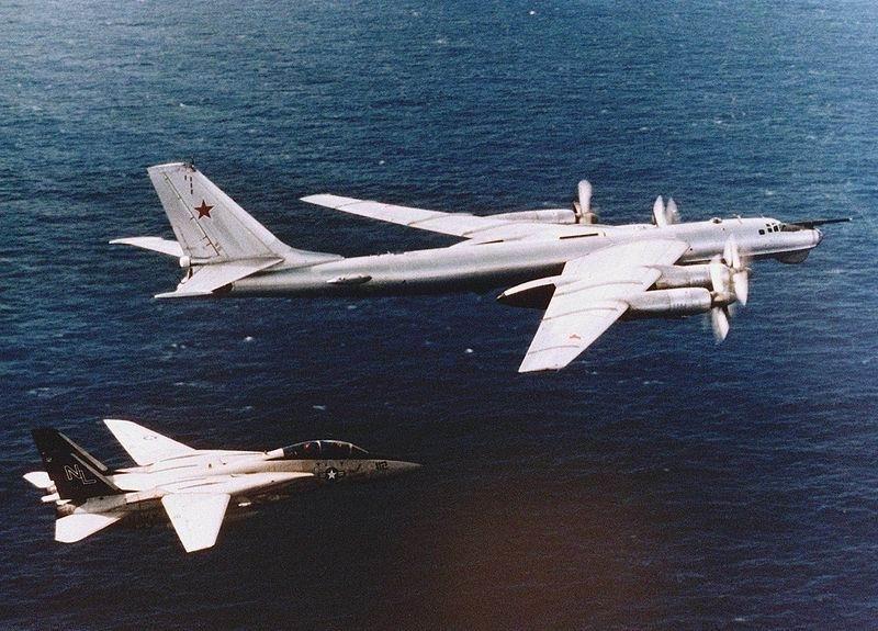
TU-95 BEAR (57)
In the late 1970s the supersonic, swing wing TU22M, known as the Backfire bomber, entered service. This was powered by two turbojet engines. It was a much more powerful aircraft than the Bear having a cruise speed of 900km/hr and an operational range of 5,000km. It could carry three nuclear capable cruise missiles with a range of 400km and up to ten short-range (150km) air to ground missiles. Its speed and range made it a major air defence threat.
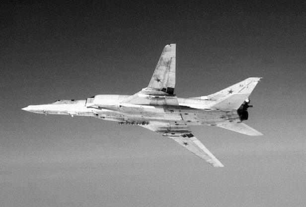
TU- 22 BACKFIRE (58)
LINESMAN
At the end of the 1950s the speed of Soviet bombers increased and the volume of civil air traffic also increased. Furthermore there were concerns that the UK radar system could be “blinded” by Soviet jamming aircraft. Trials conducted with the ROTOR system in the late 1950s showed that it was too slow in responding to fast flying Russian bombers. The time taken for operators to detect and recognise threat aircraft amongst the friendly and civil traffic and pass their details through the various layers of command became too long. Hence intruders would be able to launch their weapons before being attacked by interceptors.
It was therefore decided to develop a new, computerised, defence system with new radar sensors. This system was codenamed “LINESMAN”. The command centre for Linesman was housed above ground at West Drayton where it was co-located with the National Air Traffic Control system. Rapid interchange of information about civil aircraft flight plans was therefore possible .Radar signals from all UK defence radars were transmitted by microwave link to the command centre. Once aircraft had been detected by operators, tracks were maintained with the aid of computers and the data was processed to generate an air picture with all aircraft identified into categories.
This picture was used by the defence commanders in planning the defensive priorities and it was sent out to local aircraft control centres in the various air defence sectors of the UK.
The primary purpose of the Linesman system was to detect an incoming Soviet nuclear armed attack in time to ensure that the UK nuclear armed bombers were airborne and on their way with a nuclear response. This was a deterrent strategy that was known at the time as Mutually Assured Destruction (MAD).
TYPE 85 RADAR (59)
In addition to the computer system the Air Defence radar system was further enhanced with the high performance Type 85 Radar shown above (3Ghz). This very high powered radar had an antenna measuring 60ft by 22ft and several of transmitter horns producing
a number of overlapping narrow beams in elevation. This enabled it to measure height accurately. It also had many features to minimise the effects of jamming.
The Linesman system also had the Type 84 Radar (1Ghz), a nodding height finder and a unique sensor called Winkle (below) capable of locating aircraft that were attempting to jam the radar system.
WINKLE (60)
LINESMAN ERA AIR DEFENCE AIRCRAFT
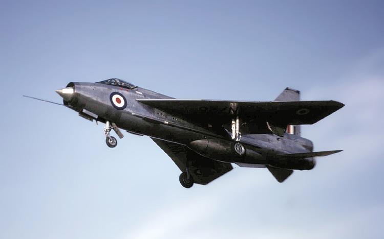
English Electric Lightning (61)
The English Electric Lightning aircraft served the RAF from 1959 to 1988. It was the only British designed and built fighter to serve with the Royal Air Force that was capable of speeds in excess of Mach 2 with a top speed of 1,500 mph, a combat range of 400 miles and a ceiling of over 60,000ft. It was armed with two Red Top heat-seeking missiles. Early versions of this aircraft were very limited in range but later versions had additional fuel tanks fitted.
In 1970 the Phantom aircraft was purchased from the USA and it was introduced into service in the Air Defence role to supplement the Lightning. It was in service until 1988. It had a maximum speed of 1,400 mph a combat range of 540 miles and a ceiling of 60,000ft. It was superior to the Lightning in policing the Northern UK airspace against the frequent incursions by Soviet Bear and Badger aircraft due to its increased operational range, powerful radar and improved armaments.
The Phantom could be armed with four Sidewinder (IR) and four Sparrow radar guided semi-active air-to-air missiles. The lower picture shows additional fuel tanks to increase the range of operations.
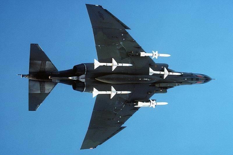
PHANTOM (62)
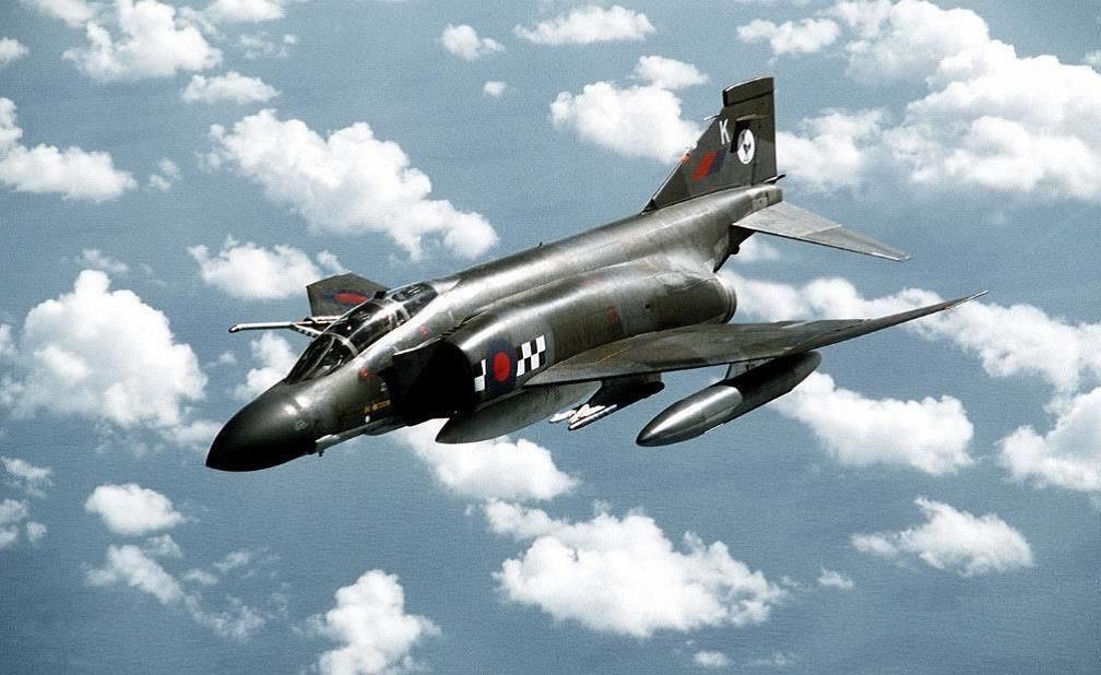
PHANTOM (63)
FURTHER IMPROVEMENTS TO THE AIR DEFENCE SYSTEM
In the 1980s there was a change in defence strategy as it was recognised that we might not be facing a threat of an unannounced nuclear strike but that there might well be a period of conventional war perhaps leading to a later nuclear attack. The vulnerability of Linesman, with its above ground control centre, to attack with conventional weapons not requiring a nuclear response was recognised and the RAF embarked on the development of a new, physically robust, computerised system using the refurbished deep bunkers of ROTOR.
This new system, the ground based elements of which were known as IUKADGE (Improved UK Air Defence Ground Environment) was designed to be able to continue working during a non nuclear battle even if some of the computerised sites had been destroyed. Not only were the main control sites buried in deep bunkers but they were designed so that, in the event of the failure of one of them, its functions could be performed from another site
. New transportable radars (above) were installed so that if battle damage occurred a replacement could easily be put in place. A typical radar had a large (24 ft high by 40 ft in width) flat antenna that could be transported by lorry.
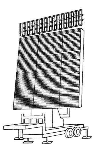
ARRAY RADAR (64)

AEW (65)
The ground radars were supported by the Airborne Early Warning (AEW) aircraft providing good “over the horizon” radar cover.
First delivery to the RAF was in March 1991. The E3D Sentry aircraft shown here is the UK’s principal Airborne Warning and Control aircraft (AWACS). The aircraft has ten hours endurance un-refuelled and houses a rotating radar in the 30ft diameter radome giving it a detection range in excess of 200 miles against low flying targets.
In addition to its role as an early warning radar enhancing the capability of ground radars, the AEW aircraft can be used as a control centre to direct fighter aircraft to their targets and as a sector operations centre to manage the air battle should the ground system have been destroyed.
There are some 16 control positions in the control suite shown below. The aircraft has the capability to exchange digital data rapidly and securely with other aircraft and with the ground defence network.
The aircraft can be rapidly deployed to the regions giving concern and can be used for UK air defence and in a wide range of other operations. The RAF has seven E3D and needs to have at least six of them available at any time.
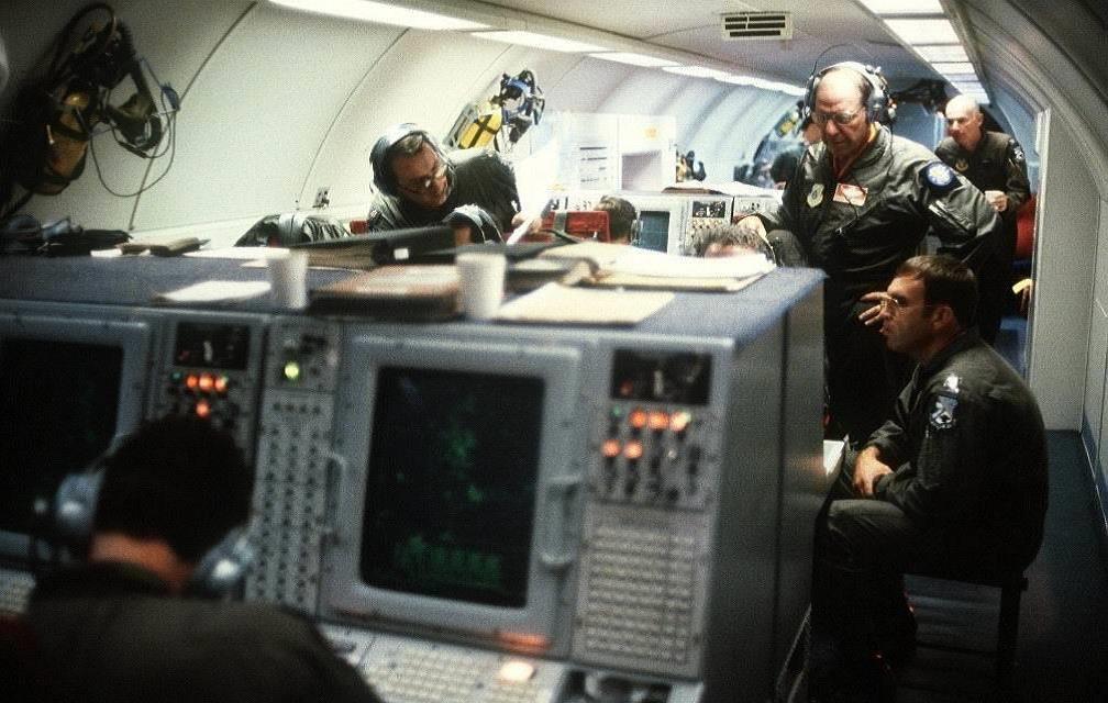
AEW Interior View (66)
AIR DEFENCE AIRCRAFT OF THE 1980s AND BEYOND
The Tornado Aircraft (shown below) entered service with the RAF in the mid 1980s as a result of a multi-national development programme. Production ceased in 1998. The F3 variant replaced the Phantom.
It was the first RAF swing wing aircraft and had a top speed of Mach 2.2. It was armed with four Skyflash radar-guided missiles and four Sidewinder infra-red homing air-to-air missiles providing a fire-and-forget capability. Some 100 RAF F3 Tornadoes have been upgraded to carry the recently developed Advanced Medium Range Air-to-Air Missiles (AMRAAM) a radar guided fire-and-forget air-to-air missile.
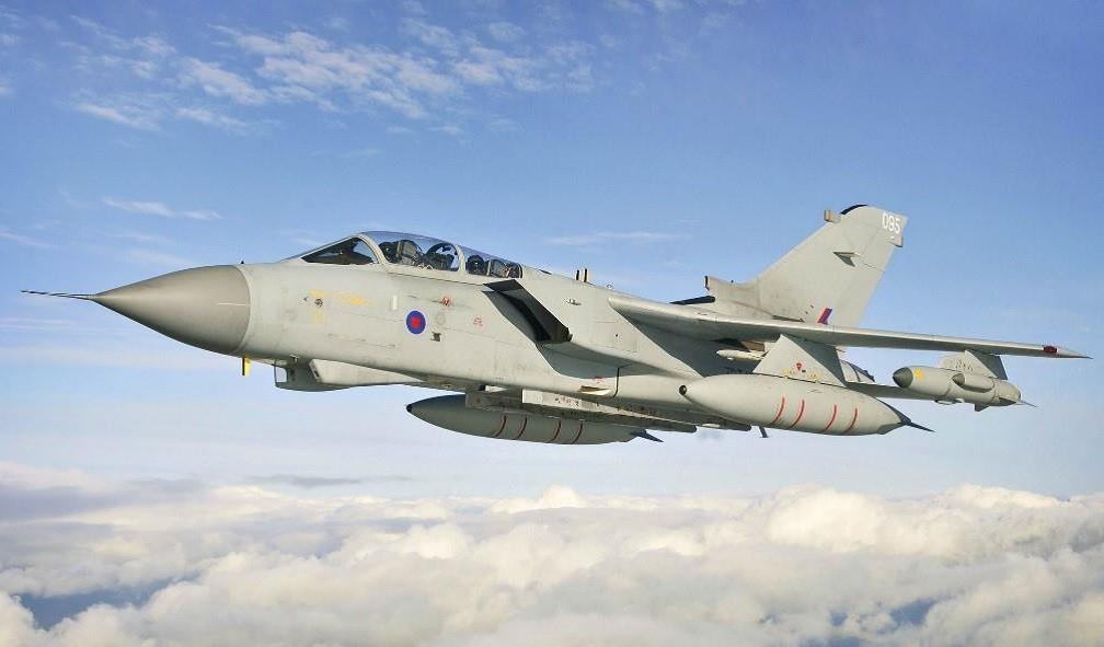
TORNADO (67)
The air defence capability was enhanced with the introduction, post 2006, of the multi-role Eurofighter Typhoon aircraft (below). The RAF planned to purchase 232 of these aircraft which were developed by a multi-national consortium of the UK, Germany, Italy and Spain.
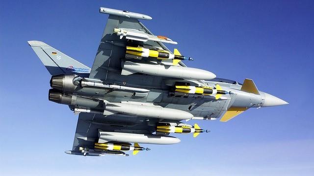
EUROFIGHTER (68)
The airframe is constructed mainly from Carbon Fibre Composites, lightweight alloys, titanium and glass reinforced plastics giving the aircraft a reduced radar signature.
Eurofighter Typhoon will be equipped with two infra red guided Advanced Short-Range Air-to-Air Missiles (ASRAAMs) and four AMRAAMs. These missiles provide the aircraft with the ability to attack before visual range hence, hopefully, before they become vulnerable themselves. Top speed is 750 knots at low level or Mach 2 at high altitude.
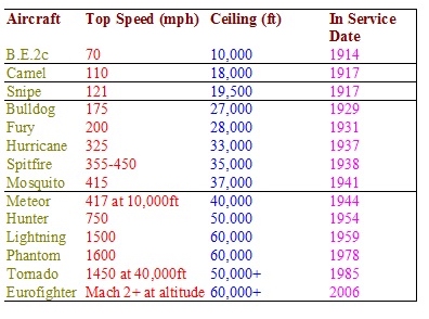
AIR DEFENCE AIRCRAFT PERFORMANCE DURING THE 20th CENTURY
ELECTRONICS
The invention of radar and other electronic systems were powerful factors in achieving victory in the second world war.
In the modern era the need for advanced electronics has become even more important. The air-to-air battle is a battle between the electronics ingenuity of the defender versus that of the attacker.
The modern fighter is packed with electronic systems. Some of the more important are listed below.
AIRCRAFT ON BOARD ELECTRONICS
Ground-to-Air communications to enable ground control of the aircraft as necessary.
Secure air-to-air and air-to-ground networking for information distribution between aircraft and the ground defence system.
Airborne multifunction radar to achieve intercept with the enemy and to control air-to-air missiles.
Radar warning receiver to alert pilot to threats.
Missile approach warning radar to warn of immediate danger.
Jamming Systems to confuse enemy Radars.
Chaff and flares to deflect enemy missiles.
SNAPSHOT VIEW OF THE AIR DEFENCE PROCESS AND THE EVOLUTION OF THE SURVEILLANCE AND CONTROL SYSTEM.
The Air Defence process has a number of stages to it that have not in principle changed over the years. Aircraft are first detected, hopefully for long enough to determine the aircraft heading. The tracks from radars with overlapping coverage are combined, aircraft are recognised into various categories such as friendly, hostile and unknown. The threat direction and strength is determined, the friendly defence resources are determined, an appropriate response to the threat is decided and the friendly aircraft are directed towards the threat. After engagement the friendly aircraft is directed to the most convenient airfield for refuelling and if needed for re-armament.
The Chain Home Radars detected aircraft positions, reported them to the track filter room where aircraft were categorised and overall raid areas were identified. The air picture so generated was passed to the Air Defence control room where, taking note of available defence resources, the battle plan was decided. Instructions were given to the various defence sector control rooms who then managed the local battle by sending fighters to meet and visually make contact with the enemy.
After the scanning Radar Type 7 was developed and installed the sector control rooms had access to a local air picture that enabled them to direct defence forces towards enemy raids in a process known as Ground Controlled Intercept (GCI). This process was enhanced when our forces were fitted with airborne intercept radars to make it easier for friendly aircraft to close in on enemy forces.
With the installation of the Type 80 Radar that had a long range capability, the need to have a separate radar for early warning (Chain Home) and for GCI (Type 7) was removed and the Type 80 performed both functions. Detection and tracking of aircraft was a fully manual operation requiring close attention to the radar display.
In the computer based Linesman system all radar data was sent by microwave link from the radar sites to the processing centre at West Drayton. Here aircraft tracks were initiated and maintained manually but positional updates were assisted with the aid of the computers. Aircraft tracks were categorised (recognised) with the aid of computer generated displays of known civil and military traffic sent from the civil aviation system also at West Drayton. The Recognised Air Picture was then sent to regional sector control centres who managed the response to the threat.
In the automated IUKADGE system aircraft tracks were initiated and tracked automatically at the radar sites and computer based aids assisted in the categorisation of aircraft. Information was also gathered by the use of airborne radar sensors and ground based mobile sensors.
A REASON FOR CONCERN?
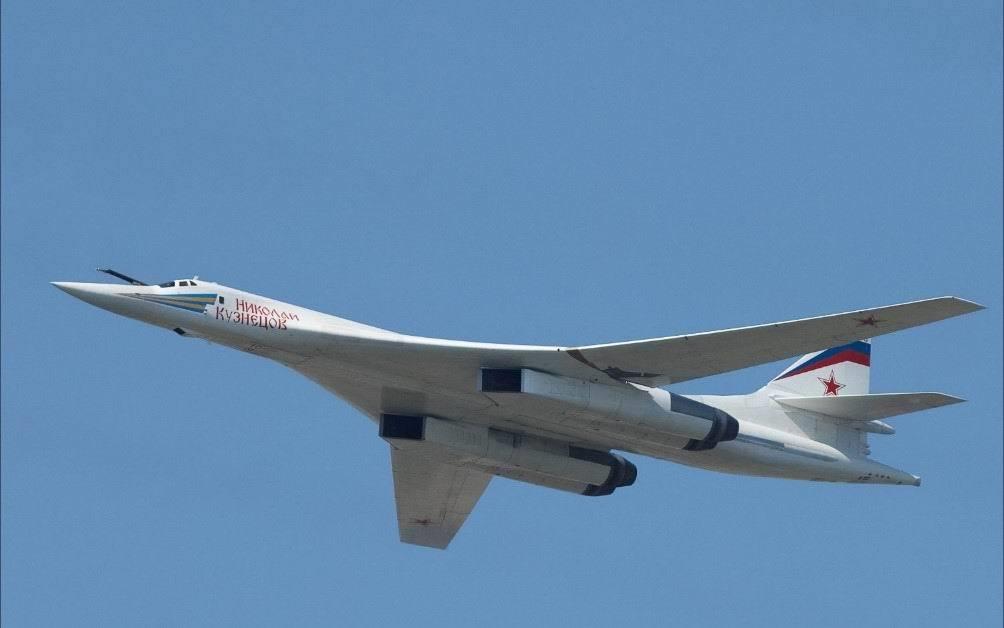
TU-160 BLACKJACK (69)
The relationship of the West with Russia is, compared to the Cold War days, much better. However the price of peace is eternal vigilance. Typical of the capability of the modern bomber is the Tu-160 supersonic strategic bomber which has an operational range of 14,000km and a service ceiling of 16,000m. The maximum flight speed is 2,000kph at high altitude and 1,030kph at low altitude.
Delivery of this bomber to the Russian Air Force started in May 2000 and many aircraft are now in service. The purpose of the aircraft is the delivery of nuclear and conventional weapons deep in continental theatres of operation. The aircraft has all-weather, day-and-night capability and can operate at all geographical latitudes.
.jpg?timestamp=1572024893437)
The present day UK ASACS is a robust and resilient computer-based system which uses many of the IUKADGE sites and equipment to gather information on all aircraft flying in and around the UK Air Defence Region. It categorises the aircraft to generate the “Recognised Air Picture” (RAP). The information within the RAP 80 is used by the Air Defence Commander when deciding whether to investigate or perhaps even destroy an aircraft flying in an area without permission. Information is fed into the RAP from the RAF's ground-based radars, from airborne and seaborne sensors and from the air defence systems of our neighbouring NATO partners. Information is exchanged with the civil and the military air traffic systems. Radio contact is maintained with all air defence operational traffic from the control sites. Fylingdales can provide high level radar cover for 3,000 miles across eastern Europe to give advanced warning of ballistic missile attack.
TECHNOLOGICAL ADVANCES
.png?timestamp=1572098351789)
.png?timestamp=1572098453969)
.png?timestamp=1572098524715)
THE FUTURE
Who knows how the threat will develop and what technological advances will occur in the next 100 years? The unification of Europe and the end of the Cold War have considerably reduced the local threat but distant countries can now pose a threat through the use of long-range ballistic missiles and the possibility of the spread of weapons of mass destruction. A missile shield covering Europe is possibly the answer to these distant threats.
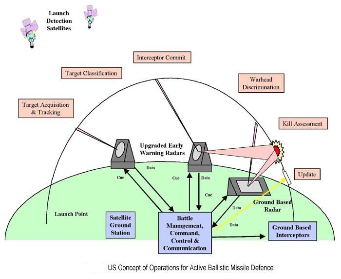
(72)
ACKNOWLEDGEMENTS
This history has drawn upon information and images posted on a number of websites. In particular I would like to acknowledge the following sites for the images they have made available. I believe the images I have used to be in the public domain though I have not been able to contact the webmaster of some of the sites to confirm this. Should some material be under copyright I will rectify when notified. JohnPrior(Ed)
Picture 1 Flyingmachines.ru
Picture 2 nrscotland.gov.uk)
Picture 3 commons.wikimedia.org
source: earlyaviator.com/archive1.htm
Picture 4 owlcation.com
Picture 5 commons.wikimedia.org
Source :Canadian Air force
Picture 6 nationalmuseum.af.mil
Source:USAF
Picture 7 shushpanzer-ru
Picture 8 IWM
Picture 9 battlefield.wikia.com
Picture 10 skylighters.org
Picture 11 rarehistoricalphotos.com
Picture 12 creativecommons.org/licenses/by-sa/2.0/
Picture By Peter Horsefield
Picture 13 Flickr via Creative Commons licence
Picture by Simon
Picture 14 en.wikipedia.org
Picture 15,16 Commons Wikimedia source: IWM
Picture17 flickr.com/photos/sdasmarchives
Picture18 Free aircraft images.blogspot
Picture19 Commons Wikimedia Source IWM
Picture 20 sas1946.com
Picture21 IWM .
Picture22 bfi.org.uk
Picture 25 commons.wikimedia.org source: IWM
Picture26 IWM
Picture27,28,33 commons.wikimedia.org
Picture27b en.wikipedia.org/
Picture29 freeaircraftimages.blogspot.co.uk
Photograph by Adrian Pingstone
Picture30 pxhere.com
Picture31 www.warhistoryonline.com
Picture 32 www.heinkel111.narod.ru
Picture34 commons.wikimedia.org
photo taken by Kogo
Picture 35 www.dailymail.co.uk
Picture 36 ses@snndiego.edu Steve Schoenherr
Picture 37,38 defencyclopedia.com
Picture 39,40,41,45,47,53,57,58 commons.wikimedia.org
Picture42 geocities.ws/fort_tilden
Picture43 en.wikipedia.org source IWM
Picture44 www.strangemilitary.com
Picture46 en.wikipedia.org
Picture48 marconiradarhistory.pbworks.com
Picture49 upload.wikimedia.org
Picture51 commons.wikimedia.org Source Arpingstone.
Picture52 Source Greg Goebel
Picture 55 commons.wikimedia.org Source Max Smith
Picture 56 www.braw.co.uk Source: Norman Murphy
Picture59,60 From the GEC review 98
Picture61 commons.wikimedia.org Source Arpingstone
Picture 50,62,63,65,66,69 commons.wikimedia.org
Picture67,68 www.flickr.com
Picture70 akrepublicans.org
Webmaster ;- thepriors35@gmail.com